At a recent (last night if you are reading this on the day of the posting) LARUG Meeting Cody Nowak presented a little tutorial on how to hook up Revit with your favorite RSS feeds. I trust you will use this for purely business purposes ;-)
If you'd like to keep in touch with said LARUG just check out and friend us up or follow us using these Twitter and Facebook pages and don't forget the LinkedIn page... Friends Rule!!! Communication Rules too...
BTW: If you can't download the PDF from Scribd use This Link.
C Nowak's Revit RSS How To
Download at will...
Thursday, October 21, 2010
Thursday, October 14, 2010
Are Revit Elevation Views Leaving You Flat? Another How-To-Solve-It with Filters
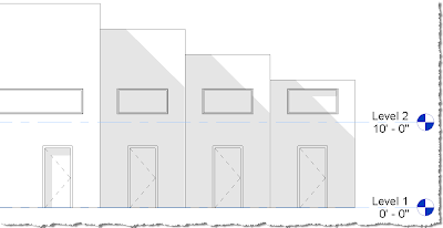
I want something like this:

HTF can we easily get Elevations (Sections, etc.???) to have distinctions in their graphic representations as they fall further into the distance from our picture plane? You know, get items to appear as if they are fading away or appearing lighter, the greater the distance away they are... without using cruel workarounds like the less than optimal ‘Linework’ tool (read ‘Linework tool’ as the “waste(r) of time and I will probably be forced to rework these over and over as the project progresses” tool) or the shunned Drafting Lines themselves (Please say you don’t use lines). SO how do we??? Hmmmm…
OK, you are about to get the answer to those questions and get one main Best Practice and another one or two solutions that are a less recommended due to their major documentation limitations. Therefore soon you’ll be able to say goodbye to the “flat, dead, fugly, OOTB elevation problem”. YAAY!!!
Although I have heard a lot of comments and complaints through the years about how dead, flat & frankly fugly looking Elevations and Sections can look in Revit, I think it reflects more on us, rather than solely on Revit (but both have been at fault, if you ask me).
I do not want something like this:
 Oh, the reason I say it’s an ‘us’ thing is that there are solutions… If you haven’t found solutions or heard of any (yet) let this be a new beginning; but if you do know of some and one has been to use filters and you have not shared it with the Revit community at-large then I say shame on you!!! Where’s the love??? If you have shared it I could not find it on the weboblogotwitosphere so perhaps marketing needs work?
That diatribe now over, we can continue :) It’s time to buck up partner, there is a really powerful cure (Hint: #2 is the cure I am speaking about).
The two methods we will discuss herein include:
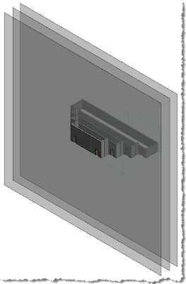
1) The Old School Glass Obstructer Method (See Image 1 below)
Not as recommended as the next method is for a CD set elevations, but useful for presentations and ancillary 3D views/3D elevations, etc.
And finally that Best Practice:
2) The Filter Method (See Image 2 below) Yes. There it is finally, your recommended Best Practice!!!
 (Image 1)
 (Image 2)
These two workflows (if you so choose to use) can also be visually pleasing when used in consort with one another… even though the glass-obstructers need a bit of management via Worksets; just test the output before committing to print the whole set or committing to pronouncing the Glass Method to be your firm’s best practice!!! Look out for the Annotation limitations listed further on, in the step-by-steps for creating The Old School Glass Obstructer Method also; that’s a huge problem with this possible solution.
 (Image 3)
Hybrid Filter-3D Elevation/Glass Obstructer Method –Again, great if you don’t want to annotate the views!!! (Why? See Image 4)
 (Image 4)
If you employ The Old School Glass Obstructer Method (step-by-step below) and think that you want to annotate the 3D “Elevation” views you have a harsh reality coming… You can only use Text. Period.
No Dimensions, no Tags, no Keynotes, no etc…
Why? Because Dimensions, Spot Elevations & Spot Coordinates are only available in 3D views set to a non-flat direction, such as isometric, that’s why. If we look at this logically the flat 3D views only appear flat, thus these tools would probably hit unknown parts of the project, not what we want.
The Old School Glass Obstructer Method Step-by-Step:
1) Create 1” thick walls with a new material that I like to call Glass Obstructer; In the examples herein the material is setup thus (See Image 5)
 (Image 5)
Glass Obstructer Material Settings
2) Place these walls where they need to be (obviously)
 (Image 6)
 (Image 7)
 (Image 8)
Filter Planning Matrix
2) Create Elevations (of course)
3) View Ribbon > Graphics Panel > Filters Tool (See Image 9)
 (Image 9) The Filter Tool
 (Image 10) Filter creation
a. Use the info from your Filter Planning Matrix
BTW: This matrix can be scaled to be useful for any filter plus variants can be used to plan & manage every possible setting in Revit; especially useful since one should NEVER save their old template files into a newer version…Unless you want to lose functionality!!! Really!!!
b. Assign the filters to the appropriate objects; in this case I used only Walls
c. Setup the filter rules
OK get ready: In this scenario I am using an ADSK OOTB template so I simply used the Instance Parameter “Comment” for the assignment portion of this solution… On a real project I suggest that you setup custom/instance/Project Parameters corresponding to each elevation view, for the Objects to be overridden (walls in this case): perhaps they look similar to Image 11 & 12's List of Potential Instance Parameters for Walls to be overridden using the Filter Method:
 (Image 11)
Parameter Setup Example
 (Image 12)
Wall Properties/Parameter value Example
With these setups assign each wall’s instance parameters with the number that corresponds to the (to be) overridden line weight setting (1 for 1, etc.)
Are you with me so far? It is simpler than it appears after a while… Plus very powerful and should open your imagination up to use filters rather than the horrendous Override in View!!!
5) Open one of your elevation views
a. Type VV (Visibility Graphics… Yeah VG works too but I don’t like moving my finger that half inch :))
b. Select into the Filters Tab and Add all of the necessary filters (See Image 13) –That’s right: neither shift, nor Ctrl work here; to select these all just click them individually… *#@! Software Developers can’t seem to make their dialogues work consistently yet… Yikes!!!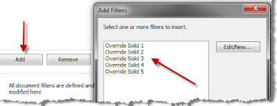 (Image 13)
c. Next, while still in the elevation’s Visibility Graphics Chose the corresponding override Weight for each filter (Projection Lines definitely, Cut Lines ??? Hmmm is that where we’d mess with our sections??? You bet!!!). (See Image 14)
 (Image 14)
Choosing the overrides per filter
d. Click OK and you’re almost there…
I have to take a pause here and admire the strength of filters. Don’t worry, we’re almost Finished!!! (Let's take a look at the (now filter-overridden) View again)
 AHHHHH... That’s a whole lot better!!!
Finally: Oh wow, there's more? Well, yes... we want to push these filters/overrides more methodically than by manually repeating the V/G, filter addition & overriding, don’t we? YES; you had better have said yes!!!
6) Go over to the Project Browser
a. Right-Click the view you just overrode the line weights for
b. Select “Create View Template From View”
c. Name the View Template with a useful name (follow conventions)
d. Un-check all check boxes except “V/G Overrides Filters” (See Image 16)
 (Image 16)
Sweet 16: View Template
7) Apply this View Template to all necessary elevations and if you have set all the walls with the appropriate integer value for those parameters you created you will have similar results as these!!!
Good luck and let us know what great uses you use filters for that may be out of the ordinary.

HTF can we easily get Elevations (Sections, etc.???) to have distinctions in their graphic representations as they fall further into the distance from our picture plane? You know, get items to appear as if they are fading away or appearing lighter, the greater the distance away they are... without using cruel workarounds like the less than optimal ‘Linework’ tool (read ‘Linework tool’ as the “waste(r) of time and I will probably be forced to rework these over and over as the project progresses” tool) or the shunned Drafting Lines themselves (Please say you don’t use lines). SO how do we??? Hmmmm…
OK, you are about to get the answer to those questions and get one main Best Practice and another one or two solutions that are a less recommended due to their major documentation limitations. Therefore soon you’ll be able to say goodbye to the “flat, dead, fugly, OOTB elevation problem”. YAAY!!!
Although I have heard a lot of comments and complaints through the years about how dead, flat & frankly fugly looking Elevations and Sections can look in Revit, I think it reflects more on us, rather than solely on Revit (but both have been at fault, if you ask me).
I do not want something like this:
 Oh, the reason I say it’s an ‘us’ thing is that there are solutions… If you haven’t found solutions or heard of any (yet) let this be a new beginning; but if you do know of some and one has been to use filters and you have not shared it with the Revit community at-large then I say shame on you!!! Where’s the love??? If you have shared it I could not find it on the weboblogotwitosphere so perhaps marketing needs work?
That diatribe now over, we can continue :) It’s time to buck up partner, there is a really powerful cure (Hint: #2 is the cure I am speaking about).
The two methods we will discuss herein include:
1) The Old School Glass Obstructer Method (See Image 1 below)
Not as recommended as the next method is for a CD set elevations, but useful for presentations and ancillary 3D views/3D elevations, etc.
And finally that Best Practice:
2) The Filter Method (See Image 2 below) Yes. There it is finally, your recommended Best Practice!!!
 (Image 1)
 The "Glass Obstructer” Method: Not bad, but perhaps not best either
 (Image 2)
 Filter Method: Best practice (at time of this post at least. :))
These two workflows (if you so choose to use) can also be visually pleasing when used in consort with one another… even though the glass-obstructers need a bit of management via Worksets; just test the output before committing to print the whole set or committing to pronouncing the Glass Method to be your firm’s best practice!!! Look out for the Annotation limitations listed further on, in the step-by-steps for creating The Old School Glass Obstructer Method also; that’s a huge problem with this possible solution.
 (Image 3)
Hybrid Filter-3D Elevation/Glass Obstructer Method –Again, great if you don’t want to annotate the views!!! (Why? See Image 4)
 (Image 4)
Text is the only Annotation available in flat oriented 3D views :-(
If you employ The Old School Glass Obstructer Method (step-by-step below) and think that you want to annotate the 3D “Elevation” views you have a harsh reality coming… You can only use Text. Period.
No Dimensions, no Tags, no Keynotes, no etc…
Why? Because Dimensions, Spot Elevations & Spot Coordinates are only available in 3D views set to a non-flat direction, such as isometric, that’s why. If we look at this logically the flat 3D views only appear flat, thus these tools would probably hit unknown parts of the project, not what we want.
The Old School Glass Obstructer Method Step-by-Step:
1) Create 1” thick walls with a new material that I like to call Glass Obstructer; In the examples herein the material is setup thus (See Image 5)
 (Image 5)
Glass Obstructer Material Settings
2) Place these walls where they need to be (obviously)
a. Ensure that these obstructers are substantially wider & taller that the rest of the project (See Image 6)
 (Image 6)
Glass Obstructers in Place (Yeah I know!!! Weird, huh?)
b. Place the obstructers in their own Workset (WS) that is created Off by Default (See Image 7)
 (Image 7)
Glass Obstructers Workset settings
3) Create a set of 3D Views; one for each desired “Elevation” (similar to Image 3 above)
a. Set these 3D Elevation Views to be aligned with a corresponding, real Elevation View or use the view-cube and set to flat orientations.
b. Turn on the WS in all appropriate 3D “Elevation’” views to get that faded look.
4) – Shadows anyone???
Now That The Not-So-Recommended Way Has Been Explained Let’s Get To The Real Good Stuff!!!
The Filter Method: A (sort of) Step-by-Step:
1) Create a filter planning matrix (See Image 8)
a. This is a Word document, where filters will be planned, so they are made efficiently, predictably and clean Excel works well too.
 (Image 8)
Filter Planning Matrix
2) Create Elevations (of course)
3) View Ribbon > Graphics Panel > Filters Tool (See Image 9)
 (Image 9) The Filter Tool
4) Create Filters (See Image 10)
 (Image 10) Filter creation
a. Use the info from your Filter Planning Matrix
BTW: This matrix can be scaled to be useful for any filter plus variants can be used to plan & manage every possible setting in Revit; especially useful since one should NEVER save their old template files into a newer version…Unless you want to lose functionality!!! Really!!!
b. Assign the filters to the appropriate objects; in this case I used only Walls
c. Setup the filter rules
OK get ready: In this scenario I am using an ADSK OOTB template so I simply used the Instance Parameter “Comment” for the assignment portion of this solution… On a real project I suggest that you setup custom/instance/Project Parameters corresponding to each elevation view, for the Objects to be overridden (walls in this case): perhaps they look similar to Image 11 & 12's List of Potential Instance Parameters for Walls to be overridden using the Filter Method:
- Elevation Override East
- Elevation Override North
- Elevation Override South
- Elevation Override West
 (Image 11)
Parameter Setup Example
 (Image 12)
Wall Properties/Parameter value Example
Are you with me so far? It is simpler than it appears after a while… Plus very powerful and should open your imagination up to use filters rather than the horrendous Override in View!!!
5) Open one of your elevation views
a. Type VV (Visibility Graphics… Yeah VG works too but I don’t like moving my finger that half inch :))
b. Select into the Filters Tab and Add all of the necessary filters (See Image 13) –That’s right: neither shift, nor Ctrl work here; to select these all just click them individually… *#@! Software Developers can’t seem to make their dialogues work consistently yet… Yikes!!!
 (Image 13)
Adding the filters to a view’s Visibility Graphics
c. Next, while still in the elevation’s Visibility Graphics Chose the corresponding override Weight for each filter (Projection Lines definitely, Cut Lines ??? Hmmm is that where we’d mess with our sections??? You bet!!!). (See Image 14)
 (Image 14)
Choosing the overrides per filter
d. Click OK and you’re almost there…
I have to take a pause here and admire the strength of filters. Don’t worry, we’re almost Finished!!! (Let's take a look at the (now filter-overridden) View again)
 AHHHHH... That’s a whole lot better!!!
Finally: Oh wow, there's more? Well, yes... we want to push these filters/overrides more methodically than by manually repeating the V/G, filter addition & overriding, don’t we? YES; you had better have said yes!!!
6) Go over to the Project Browser
a. Right-Click the view you just overrode the line weights for
b. Select “Create View Template From View”
c. Name the View Template with a useful name (follow conventions)
d. Un-check all check boxes except “V/G Overrides Filters” (See Image 16)
 (Image 16)
Sweet 16: View Template
Good luck and let us know what great uses you use filters for that may be out of the ordinary.
Tuesday, October 12, 2010
The New (New) Revit Graphics Card List is Here!!!
Without further ado: Get the current (as of the date of this post) Revit Approved Graphics Card list Here when choosing a new workstation (and I don't mean a small business or home rated computer!!!)... remember if you get anything that's not on the list or that's not followed by a green Check/+ 
then you're on your own.

then you're on your own.
Tuesday, October 05, 2010
Do you play BIM? Will You be in Vegas this December?
Nice hair... too bad I cut it...
Let's see how many people we can jam into this session at the upcoming 2010 Autodesk University (AU)
Coordinating Hot Revit® Models: How to Become a "10"
This 1-Hour session is for all All Levels of Revit User and attendee participation mandatory (ok, highly recommended)!!! Yes, this means those who show up will add to the discussion... Are you ready???
Subscribe to:
Posts (Atom)