Thursday, December 22, 2011

Fear and Loathing In a CAD vs. BIM World and a Fluffy Kitten Walk Into a Bar... A 2012 Recap

The following are 15 selected posts from the past year that I feel are still helpful. I did leave out the post on Revit Tools (no not the bad users) since there are a lot of new tools and I am considering a future post for that...

Thanks to everyone for reading, sharing, adding, teaching, voting, supporting, loving, friending, @ing, forwarding, liking, favorite'ing, this blog & me. I am having a great time growing with you all and will continue to inspire, infuriate, confound and everything else I do :-) 
-J

1) Worksharing need to knows

 2) Holograms... "To all my friends" 

3) Skinput (Not helpful 'yet' but super cool)

4) Copy Monitor (Considerations for beginner to intermediate Reviteurs mostly)

5) More Dimensions of Revit (LOOK AT THE F'ing PROPERTIES DIALOGS PEOPLE!!!)

6) What's the best computer for Revit 2012 (a popular post for readers around the world) Get ready I am going to really up the anti for next year's Revit machine needs!!!

7) (most) Everything you'll need to know about Keynoting (just hit the post, then the 2 red "HERE" links)

8) That damned Revit Cow. (Just wait until RTC2012 everyone... we are going to blow your... mind(s))

9) Programmatic uses of Revit

10) Family Considerations to considerate (yes I know)

11) Keyboard Shortcuts Just for You (and you know who 'you' are)

12) So do you want to be an Architect REALLY? -A fun break from the BIM...

13) Detailing the Revit Detailing Process (NO LINES!!!)

14) Take a Ride on The Rails (A new future is inspired)

15) OMFG Building Rigs Have Unforseen uses -Those will follow next year as well!!!
Have a great New Year and be fantastic all year!!!

BIM In Love

Tuesday, December 13, 2011

Monday, December 12, 2011

Live Renders NOT in the clouds

There is much ado about clouds, infinite computing, etc. in AEC these days... Call me leery but I just do not see full production ready solutions out there yet (YET!!!)... I know we probably will but not so much yet; furthermore some people just need to work locally for a myriad of reasons...

Well In the past I have used Artlantis as a quick rendering solution in design stages, since they have a Revit plugin to get your files natively there to play with, it's fast and you see your changes live on screen without hitting the render button... Well now I have learned of Lumion. I am getting their demo now to test and will have some results in the future...but it looks quite promising; with live animated objects such as people, water, etc...an interface that 'seems' logical and user friendly (though we will see) and all the effects and modifications & additions are live and applied on-the-fly!!!

So until I get some results here are some demos... check them both out for yourself...
As always the links are links ;-)

LUMION


ARTLANTIS

Wednesday, December 07, 2011

Oh Revit Forums You Do Love Me Don't You

A great year and great posts from around the Revit-o-sphere and I am happy to announce that a tutorial-post I created (based on some collaboration with Marcello Sgambelluri), called Make S Ride on The Rails (yes that's a link) has been voted as October's Post of the Month over at the Revit Forum.

The Image (left) links to the RFO main page where you can vote for PotY (Post Of The Year)!!! 

Voting seems to be a theme this month, huh!!!

Some pretty rarefied air up there with the other Revit Forum-eers & winners and I am quite happy about that since I must admit, I dig the attention: even though it's the post itself and not me personally that won but I can delude myself easily enough: BTW "we" call that 'dancing'!!!

Next: voting is ALIVE NOW so if you have it in you & are a member of the Revit Forums go share your power!!!

Can we get a groundswell and win that too? I am not sure, but do go and vote for your 3 favorites and know that whomsoever comes out on top it's a win-win for all of us #BimModelingFluffyKittenKillas!!!


Tuesday, December 06, 2011

Board Of Directors? Vote New Directors Onto The AUGI Board

Who to vote for? (by hitting the image left)

Me of course!!! (OK OK others as well :-))

There have been a few times where I felt that AUGI could have benefited from a Board of Directors that displayed a passionate and unique perspective such as mine, so when I was asked to throw my hat in for consideration I felt that running for it seemed a logical expression of my desire to inspire and improve our industries. 

Many of you who know me: whether socio-digitally, personally or professionally: know that I will add a clear, creative and essential voice to the Board: if elected.

This is one of those (small) times where we can stand together and make our voices truly heard, while building a stronger ADSK community at the same time. 

That's what voting is for, right; getting constituent's voices heard and making life a little better? This time; unlike the electoral college system your voices ARE the voices heard!!!


AUGI needs to fill some seats and voting is open through Thursday December 15th 10:59pm GMT (See this Zulu (GMT) Time Zone Guide);  You can vote at: http://bit.ly/rFoQu2

If you do not yet know; AUGI (Autodesk User Group International) is a volunteer organization and is free to join, so whether or not you vote please join (if you already haven’t) as there are benefits for all Autodesk Software Users to be had through AUGI at http://www.augi.com/  


I hope you can find the short time (outside of business hours) to show your support & vote for me in this endeavor. 

There are others running and all of our the candidate information is available and can be found at: http://bit.ly/rNDluY I suggest that you read all of our posted documents as well as our responses to questions posed and make up your own minds (obviously)...


Thank You All Very Much and...

I approved this message :-)

Wednesday, November 23, 2011

A BIM Model and a Fluffy Kitty Walk Into A Bar

<Edit 08/04/2012) The following post has been made irrellevant by the Divide & Repeat commands!!! Well, except for maybe horrible the jokes perhaps...BTW: The drink below is not good!!! Try Tequila with a splash of red food coloring at your next party though (still unmixed) <End Edit>

Bartender says "What will you have BIM Model?", The fluffy kitty (AutoCAT) suddenly dies a bloody death and BIM Model says: "I'll have some of that...again"
Hmmm...A new drink: the "Bloody Fluffy Kitty" It's a double shot size glass of "Tequila, splash Benedictine, & Hot Sauce (unmixed)" Yumm... let's try that out... "I'll have a bloody fluffy kitty please" ... why yes i think that works!!!

So... after completing this post I realized that I'd only grade this Rig family an A-
The minus is because of the two mistakes (not following my own advice by not fully writing everything out first).
Error #1) Numbering of points should have been: P00-P35 
That way P00 would be on 0° and all others would have related to their 10° spacing
Error #2) Naming of Minor points should have been: Minor P01- Minor P35 
That way the naming would be simpler due to copy/paste efficiencies, like I realized when naming the Ellipse Points.
Plus some of the steps like 1a & 1B should come after 1c & 1d but that's life... there's beauty in imperfection...
That said: on with the... BIM Modeling MEEEOOO O OWWW GURGLE GURGLE
XD

Crap, now we have another dead kitty :-( ???


Today we will look at creating a Rig to allow some nesting. You should consider recreating this type of Rig if you answer yes to any of the following (or have any other reason not mentioned):
1) Do you need 'dimensions' to get an ellipse built by someone?
2) Do you want to get better at building Adaptive Components & the use of Points?
3) Do you want to hone your problem solving skills (even just for the sake of doing it)?
4) Do you love fluffy kittens
5) Do you like to say "BIM Model"

Well the last two questions are just a BIM joke (wow I hope it's not really killing those cute little kitties) that states: (Saying "BIM Model" = 1 Fluffy Kitten Killed) I didn't make it up but I sure continue it (insert evil laugh). I am going to start to use "Saying BIM Model Kills a Fluffy Kitten" as parameter names in the future!!!

Saying "BIM Model" can be fun and I don't feel bad for saying "BIM Model" or writing "BIM Model" because of how I define BIM and BIM Models... According to me:
BIM is a process that creates everything necessary to procure, design, build and run Architectural projects. So saying "BIM Model" is just like saying "3D Model" which are but one part of the process, BIM Models are not the process itself... Take that fluffy kittens...

The processes herein assume that you will flex at each step, so if you don't have good family creation habits in Revit you should expect to create havoc and a broken family... Now you can't say you weren't warned... It's not Revit's fault if we are lazy, thoughtless or simply don't know how to validate and QA/QC our work as we go... I cannot stress enough that Revit family creation need flexing/validation at each step... In order to keep from raising super needy (Revit) families we cannot be enablers, we must be strong and uphold our values!!!

Well, anyhow...

I find that rigs are useful and just as other Artists, Designers, Modelers, Builders, etc. have always used rigs, so do I...

With rigs we can build things one time and adapt them for many uses... The imagination is the limit to what can be hosted to these rigs. What other uses can this be fit into? That's for you to define... If you think creatively and open then you can/will find many potential uses, if you think positionally and closed and don't look for potential, etc. then you might as well stop reading right here. -I am just saying :-)

OK Onto the post
Having "some" people build ellipse shaped constructions can be a pain... I have given Contractors several methods, including the 'string method', chock full of the necessary dimensions and for one reason or another that wasn't going to work according to them... I have resorted to printing 1/4 of entire elliptical rooms for others, but that can be impractical for everyone. So when a colleague was having this very issue (needing a detail with dimensions) the other day I sent them a copy of the "Auxiliary Circles Method" from Architectural Graphic Standards with the explaination, as they needed a detail with dimensions to give to a builder... Here are the simple directions, similar to the Graphic Standard ones:


1)      Draw Circle of the Minor Axis Radii
2)      Draw Circle of the Major Axis Radii
3)      Draw ‘Rays’ that extend to the Major Axis Radii Circle (repeat) -The more 'the better
4)      At each intersection of Major Axis Radii (Step 2) & the Rays (Step 3) Draw Vertical Lines straight down (perpendicular to Major Axis Line)
5)      At each intersection of Minor Axis Radii (Step 1) & the Rays (Step 3) Draw Horizontal Lines straight across (parallel to Major Axis Line)
At each meeting of the lines from steps 4 & 5 make a point, join the points using ships curves, or a really good freehand, etc. and the result will be a true ellipse: As long as you join the points properly :-)

I was looking at the image above (credit Graphic Standards) and was mesmerized... looking at the image I thought "Hey, I bet that would be a fun Rig to build in Revit: and who knows maybe it will lead to other inspiration or even be useful"...

So I did, it was!!! And here it goes:
Preliminary note: I used shared parameters so if I use any of the angle parameters on other rigs or families they are ready and waiting. Look at the future!!!

Big 'R' New>Family>Generic Adaptive...

1) Create 2 Circles of different size & parametrize the radii to be:
             a) Major Radii (Under Constraints)
                  a1) Use formula: = Major Length / 2
             b) Minor Radii (Under Constraints)
                  b1) Use formula: = Minor Length / 2
             c) Create length parameter: Major Length (Under Dimensions)
             d) Create length parameter: Minor Length (Under Dimensions)
These length parameters will be what the user changes to get different types (yes, I made them type parameters)

2) Create a Point on the base REF PLANE
     a) Change its "Offset" value to 30' (for example)
     b) Associate "Offset" to a new length parameter called: "Height"


3) Create an elliptical Reference Line at the base level
     a) Associate the big length to: Major Length
     b) Associate the smaller length to: Minor Length

4) Similar to steps 3, 3a* & 3b* except this time set the active REF PLANE to be the one set to Height (the one above but parallel to the base level Plane).
* If you want the final ellipse to taper then you will want to create separate parameters for that.

5)  Create 36 points along each Circle (yes there will be 72 of these but don't worry there will be more!!!
Note: Set one at 0° (P01) then 8 in between that and 90° (Top or 12 o'clock), then 8 more between 90° & 180° (opposite P01), 8 more between that and 270° (bottom or 6 o'clock) and 8 more between 270° & 0°: totaling 36) -This will allow one point every 10° ...logical, yes?
      a) Host the points to the circles (they get small)
      b) Set them all to "Angle" under 'Measurement Type'
      c) Name them (tedious but it really is useful and necessary) I used the following:
           c1)  P01-P36 (for the major points)
           c2)  P01 Minor - P36 Minor (for the major points obviously)
I should have used :Minor P01", etc. as a naming convention since copying & pasting that would have made the tedium a bit less.

      d) Remember those shared parameters I mentioned earlier? Well here's the time to create them:
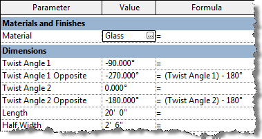
           d1) Create Angle shared parameter "Start Angle" (this will be set to 0° and linked to P01 through it's formula... See image of all parameters, below)...
           d2) Create Angle shared parameters called P01 through P36 (these are what points P01 through P36 are associated to, of course)
           d3) Associate each pair of corresponding points to these shared parameters (P01 to P01, etc)

Did I mention the formulas I used for each of these? Well, look at the image below for all of the parameters I used (Note that I probably should change them from "constraint' and organize them under 'Other' -which I normally don't use but in this case it would be much easier for the end user)...


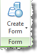
 6) Create 'Splines Through Points' for all 36 pairs of corresponding points
      a) Select a pair of corresponding points
      b) Hit the 'Splines Through Points' tool (see image below)
      c) This turns them into Reference Lines: do that for all pairs...


Phew: Now that we have done all that more fun begins...

Remember: breathe...

Ellipse Reference Points
These will be the completion (???) of the rig and they will move in direct relation to their corresponding points along the Major & Minor Radii since we will constrain them so... These are similar to the points that result by intersecting the lines from the Auxiliary Circles Method found in that Graphic Standards image shown earlier.

Name these ellipse reference points properly, like: Ellipse P02, etc. -As you will see we won't need Ellipse P01, Ellipse P10, Ellipse P19 or Ellipse P28. Why? Only points along the ellipse will want to be visible and...Points 'P01', 'P10 Minor', 'P19' & 'P28 Minor' will all fall on the ellipse as a function of nature or physics or math, etc. as they will be at the 12, 3, 6 & 9 o'clock positions of the Radii...

So we will set all the points that fall on the ellipse to the visibility parameter "Ellipse Reference Points" (you know, points 'P01', 'P10 Minor', 'P19' & 'P28 Minor' and the 32 other "Ellipse Reference Points" we are about to make).

The reason for their visibility? So we can dimension them at the project level...one main point for using such a rig (but not the only one by far!!!) How about making a dynamic... (you'll have to wait to the end of this moderately epic post for the conclusion of that sentence...) Now back to creating the Ellipse Reference Points...


Go to your 3D view & set it to "Top" and make sure that P01 is at the 3 o'clock position; then open a plan view (with view range set correctly to see all you need) and tile these 2 views to work functionally.

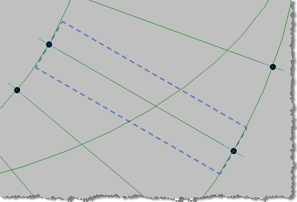
7) Set the active Reference Plane to be the flat plane from Points 'P02' & 'P02 Minor' (not shown in the image at left but at least the image shows a flat ref plane, along one of the Reference Lines :-) and that's the ...point... pun intended.

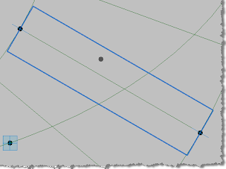
8) Place a point on that Reference Plane, do not place it on any objects such as the line itself, etc.
-See image below for these next steps:
      a) Name the point per your planned convention
      b) Change the 'Show Reference Planes' value to "Always"
      c) Associate 'Angle' to the corresponding Radii Point's angle parameter
      d) Check the 'Mirrored' box
      e) Check the 'Flipped' box

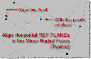
      f) Align & lock the ellipse point to the Minor Point, not the Minor point's ref planes but the point itself.

The ellipse reference points' ref planes will be used to align to though. Confused? See the image left.
To reiterate: The Minor "Points" are the Align "TO" object (1st Align click), the Ellipse Point's "Horizontal REF PLANE" is what we Align up to that (2nd Align click)


      g) Align & lock the same ellipse point to the Major Point, not the Major point's ref planes but the point itself.

The ellipse reference points' ref planes will be used to align to though. Confused? See the image left.

To reiterate: The Major "Points" are the Align "TO" object (1st Align click), the Ellipse Point's "Vertical REF PLANE" is what we Align up to that (2nd Align click)
Alignment for these Ellipse Points: Point to Planes...Point to Planes...

Once I have created the first of these aligned/locked Ellipse Points I flex the "Start Angle" parameter, just to see if they work properly...I do not continue unless they work...

That flexing (32 times) may seem tedious but since I will use this Rig for actual constructions (Hmmm Nesting some ___ on these points...) I need this to really work: if it was purpose built for ONLY generating points along an ellipse then it wouldn't have to flex, so most of the parameters and work would be unnecessary; but for my uses and my future uses it IS necessary for the angle parameters to work and all of these points need to move in concert with one-another.

NOTE: Ellipses are perfectly symmetrical so if you need a simple rig for dimensioning an ellipse juts do this kind of thing for 1/4 of the rig and just let the builder transpose the dimensions around the object... But I want to use this to layout designs, etc. so I am going all the way!!! 

ANOTHER NOTE: You had better use dimensions set to their best possible limit (1/256") or else these will never get built even nearly correct, if dimensions are the guide.

9) Remembering what I said previously "So we will set all the points that fall on the ellipse to the visibility parameter "Ellipse Reference Points" (you know, points 'P01', 'P10 Minor', 'P19' & 'P28 Minor' and the 32 other "Ellipse Reference Points"...)" It's now time to set them so.

      a) Select all of the Ellipse Reference Points & the other 4 mentioned previously
      b) Click the Associate Parameter button next to the field for "Visible"
If you didn't create a visibility parameter yet:
      c) Click Add Parameter and add one :-)

Once associated i set the behavior to be "on" by default... Also Instance or Type is your choice... 

Voilà an Elliptical Rig.

Hey Bartender: Yes BIM Model? I'll Have another bloody fluffy kitty now!!! So to end where we began just so much different now...


A new drink: the "Bloody Fluffy Kitty" It's a double shot size glass of "Tequila, splash Benedictine, & Hot Sauce (unmixed)" Yumm... Next time i will go over nesting some other Adaptive families into this rig for some (more) real excitement!!!


Thursday, November 17, 2011

Make S Ride on "The Rails": Tastes great, More Fulfilling

After collaboration with Marcello Sgambelluri, inspiring each other to a breakthrough of sorts on how we can model more effectively in Revit...at least for some components & objects: I posted a solution for how to create twisting geometry; using 'rails' to drive angles RIGHT HERE.

So now, it's that Revit Forum's "favorite post of the month" voting time!!!

It seems that the awesome folks at the RFO have thought enough of my post to nominate it for best of the month...WOOHOO... They even looked past my 'crying' about member statuses being goofy.

So If you would like to help me stuff the ballot boxes (or really; if you think it's a good posting) Hit the image at left to get your voice heard... The winner gets the honor of peer recognition (giving others crap :-)).

If you haven't seen the original postings hit This Blog's Post and for the back-story see the LARUG blog post...

After you vote that is!!! FYI: I did vote for others as well :-)


Tuesday, November 15, 2011

AUGI World November Issue

Great articles as always and SoCal Reviteur Brian Andresen got the cover.

Read the entire issue, as there is gold throughout!!!

As usual hit the images for the goods!!! The top image is for downloading any AUGI World issue and the image below is directly to the online version...


Friday, November 04, 2011

RTC USA 2012 Southern Hospitality here we come!!!

These timezones are fun... Although I also got this email last night @davewlight blogged it out first so I'll just link to his post!!!  Plus if you don't already visit his site regularly you should...

So go check out the RTC USA 2012 notice and we'll see you there, in June!!!

Thursday, October 20, 2011

Perception, Breakthrough, Success & Help

On To The Help!!! More Transformation for all.
One of the questions was how to correctly model a twisting element (see image left).

Marcello Sgambelluri & I took this one on. I modeled it the (now) olden way, as a generic component. I got the majority of success, where the model rotated from 1° to 76°. good since it only needs twist to 90°. but that is now a dead way to model...what I mean is, angular dimensions for rotation present inherent limitations... The other reasons for a new way of modeling is due to a breakthrough that Marcello had, that should/has inspired us all... Even people who think of themselves as Revit Heavyweights!!! 

The breakthrough came due to this simple modeling exercise, so get it? Marcello was open enough to let himself grow, even though he is already an amazing modeler It happened while he was driving into work (on his long commute) where he usually builds the pieces he is thinking about in his mind first...He knows to never stop growing & pushing himself... If that isn't using a good plan I don't know what is... PLAN FOR SUCCESS!!!

It's funny, we were talking about how that seems so obvious to us but (unfortunately) most people are too lazy (or whatever) for continuously learning & growth... it's just too much work for some... More work for 'us' I guess...

The breakthrough: Circles.
"Let things ride on the rails"... 

FYI: I rebuilt this based on the concepts that Marcello spoke of, so if I can do it...I can do it... :-) No...You can also!!!

A circle immediately gives a center & width, etc. and a nice stable place for points to host onto, no need for EQ constraints!!!


The point in the center (1) is given an offset (2 & 3) that will dictate Length -no dimension needed!!!

If the main REF PLANES are "0" then this "offset" will be the distance away from there, naturally...


 The points on the circle or 'rail' are told to be Angles & given Parameters of Twist Angle (name inconsequential) & the one that is opposite it given Twist Angle opposite (I used 1 & 2 so both sides of this could twist if desired)...


Getting this so far???

The 'Twist Angle opposite' parameters need a bit of a formula: See image left...

The "-180°" makes them  planar to one-another... Thus no EQ constraint!!! More Control, More Stability; Less Work!!!

We get the Reference Line between the points by selecting the 2 points & clicking the Spline Between Points tool and Voilà a line.

Remember to go to it's properties to turn it into a REF Line...


Repeat this process for the other ends' circle & points (no need for the "offset" point, as this RAIL wants to stay in it's planar location...


Half Width was added to each rail, to dictate the width, as we want width to be twice the circle's radius.

Simple right...

well it's simple once you are open to it, but even many seasoned pro's never thought of this... but I bet "we"...uhhh...I mean "they" will take credit for finding it :-)


...there may be others but Marcello was surely the first person I know of personally who stumbled onto this... Always pushing, always growing!!! Not even ADSK people knew this outright.

OK where were we... Oh yeah the twisting object itself... Hint: To create the surface set the opposing angle parameters to less than 90° so Revit doesn't overthink the shape and blow it up. Once created it will flex past 90°, it just needs to be created below that...

Select the 2 REF Lines (that are built onto those points on the rails) & click "Create Form" and you have another Voilà moment...

Associate Material to a new Material parameter, so you can change it from the project & you should be good... If you flexed each step of the way and were successful that is!!! If not...Try again!!!


Well I think that's enough for now...Be Great!!!

A very special Thanks goes out to Robb, Scott, Bill, Vince & everyone at Océ for hosting this great event, we really dug the space & we'll be back!!!

Sunday, October 09, 2011

Details in BIM: a Process Conceptualization

OK, Here is the paper I promised on Detailing concepts.

It has changed a bit (quite a bit) from the preview but I hope it's worth your while to read.

I read it as both inspiring, as well as heavy handed in it's assertions that one needs to hold to schedules and processes: but hey that's me...I just like to have projects that run as smooth as possible... XD

If you don't see the PDF below (that takes a few seconds (10-15+/- to load), as embedded from Scribd.com (@Scribd) then use the links way down below @ the bottom of this post.
Details in BIM a Process Conceptualization


Full Screen, Direct Link to Details in BIM: a Process Conceptualization

Link for all of J's 'Scribd' Documents

Cheers,

Saturday, October 01, 2011

Status Update & A Taste of Detail Conceptualization

Writing a bunch, beta testing a whole lot & as usual work & family take a lot of time (this is a lame excuse for not posting lately).

I will have some awesome (to me at least) postings in the near future, so bare with me :-)... For now; here's a taste:

Detailing in Revit
There are several ways to detail in Revit and each can be used to reach differing solutions and each is suitable for different documentation, coordination & construction needs. 

 
Detail Typologies
Details can be intellectualized as having two main Typologies, namely 2D & 3D.
•    There are three main types of Two-Dimensional (2D) details.
•    There are two main types of Three-Dimensional (3D) details.

Combining 2D & 3D details we can communicate Design intent, Coordinate projects & provide better, more efficient Construction Documents, telling the design story more effectively.

2D Detail Types & View Name Abbreviation Prefix(es)
DT    Drafting View Details
DS    Detail Sections
DH    Hybrid Details
3D Detail Types
3M    3D Model Views
3T    3D Details

Detail Methodology
The first steps in any successful endeavor are planning: and detailing a project is no exception.

The quantity & types of details used in a project are to be planned for throughout the project, usually beginning in the early to mid SD phase with more refinement when planning the transition to the DD phase.

Further planning & process refinement is done prior to, as well as throughout the CD phase as well.

Planning details is tracked and managed from a Schedule View, using custom parameter values input to ensure that what has been planned is being addressed, by whom & what the status is at any one time.

This planning can be done exporting schedules to other database software but that is not recommended, due to the fact that data outside of the BIM project file is disassociated and can lead to undesired inconsistencies & worse yet, errors and would require a lot of re-creation & re-coordination.

 
Use Cases
Detail methodologies can be broken out for several use cases, including: Typical 2D Details, Project Specific 2D Details, Modified-Typical 2D Details, 3D Views & 3D Details.

3D views & 3D Details will be used in conjunction with the more historically commonplace 2D details, to powerfully augment the AEC process.

The Design and Construction teams will find
both their understanding, coordination & visualization of specific conditions within the BIM project greatly rationalized, with extraordinary value when combined 2D & 3D information is leveraged in the AEC, BIM Design, Production & Construction processes…

The completion of this paper & more... "soon"...

Tuesday, September 13, 2011

Disruptive Technology at it's Finest!!!?

The clouds (costs) are falling!!!, The clouds (costs) are falling!!!

...And we couldn't be more pleased.

I am going to pull the trigger on this one for sure: @Bitcasa infinite cloud storage/sync/sharing is only $10 per month... Now we just need to wait for the impending Beta...

With the amount of data I have and the fact that I want universal access to it seems like this will be a big old HELL YEAH!!!

Hit the red links herein & the image for a review & more...

Tuesday, August 23, 2011

Got Collaborate? AUGI World Can Help


In the August Issue of AugiWorld (Out Now!!!, from AUGI of course) our friend Troy Gates has contributed an article speaking to Revit Collaboration, lending a bit of historical foundation, for us to move into the unknown future from... As always hit the links & Images for the resources themselves, The image below will get you to where you can download your own copy... The embed above is the online readable version...

Take care, -J