
On To The Help!!! More Transformation for all.
One of the questions was how to correctly model a twisting element (see image left).
Marcello Sgambelluri & I took this one on. I modeled it the (now) olden way, as a generic component. I got the majority of success, where the model rotated from 1° to 76°. good since it only needs twist to 90°. but that is now a dead way to model...what I mean is, angular dimensions for rotation present inherent limitations... The other reasons for a new way of modeling is due to a breakthrough that Marcello had, that should/has inspired us all... Even people who think of themselves as Revit Heavyweights!!!
The breakthrough came due to this simple modeling exercise, so get it? Marcello was open enough to let himself grow, even though he is already an amazing modeler It happened while he was driving into work (on his long commute) where he usually builds the pieces he is thinking about in his mind first...He knows to never stop growing & pushing himself... If that isn't using a good plan I don't know what is... PLAN FOR SUCCESS!!!
It's funny, we were talking about how that seems so obvious to us but (unfortunately) most people are too lazy (or whatever) for continuously learning & growth... it's just too much work for some... More work for 'us' I guess...
 The breakthrough: Circles.
"Let things ride on the rails"...
FYI: I rebuilt this based on the concepts that Marcello spoke of, so if I can do it...I can do it... :-) No...You can also!!!
FYI: I rebuilt this based on the concepts that Marcello spoke of, so if I can do it...I can do it... :-) No...You can also!!!
A circle immediately gives a center & width, etc. and a nice stable place for points to host onto, no need for EQ constraints!!!
The point in the center (1) is given an offset (2 & 3) that will dictate Length -no dimension needed!!!
If the main REF PLANES are "0" then this "offset" will be the distance away from there, naturally...

The points on the circle or 'rail' are told to be Angles & given Parameters of Twist Angle (name inconsequential) & the one that is opposite it given Twist Angle opposite (I used 1 & 2 so both sides of this could twist if desired)...
Getting this so far???
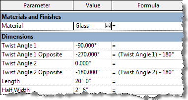
The 'Twist Angle opposite' parameters need a bit of a formula: See image left...
The "-180°" makes them planar to one-another... Thus no EQ constraint!!! More Control, More Stability; Less Work!!!

We get the Reference Line between the points by selecting the 2 points & clicking the Spline Between Points tool and Voilà a line.
Remember to go to it's properties to turn it into a REF Line...

Repeat this process for the other ends' circle & points (no need for the "offset" point, as this RAIL wants to stay in it's planar location...
Half Width was added to each rail, to dictate the width, as we want width to be twice the circle's radius.
Simple right...
well it's simple once you are open to it, but even many seasoned pro's never thought of this... but I bet "we"...uhhh...I mean "they" will take credit for finding it :-)
...there may be others but Marcello was surely the first person I know of personally who stumbled onto this... Always pushing, always growing!!! Not even ADSK people knew this outright.
OK where were we... Oh yeah the twisting object itself... Hint: To create the surface set the opposing angle parameters to less than 90° so Revit doesn't overthink the shape and blow it up. Once created it will flex past 90°, it just needs to be created below that...
 Select the 2 REF Lines (that are built onto those points on the rails) & click "Create Form" and you have another Voilà moment...
Associate Material to a new Material parameter, so you can change it from the project & you should be good... If you flexed each step of the way and were successful that is!!! If not...Try again!!!

Well I think that's enough for now...Be Great!!!
A very special Thanks goes out to Robb, Scott, Bill, Vince & everyone at Océ for hosting this great event, we really dug the space & we'll be back!!!
