Wednesday, October 24, 2007

Filters, Fire Ratings & Graphic Overrides

So you want to be a Rock n Roll Star?... Uhh wait... Oh yeah, you want to create fire rated walls in Revit and have them represent visually.... There are many options (OK, a few): One is to use a 'coarse scale fill pattern' and use a hatch pattern (that we usually have laying around from WhateverCAD). This is workable if: 1) You only need them to represent in Coarse views and 2) You only use straight walls, no curves. Not a complete solution and not my choice of them.

My choice is once again to Use Revit Like Revit; thus we will leverage Filters and Graphic Overrides to get this job done to some duplicated Object Types (or do you have them created already?) ...Hmmm...Maybe these should be built into my Project Templates, as well...

In either case we endeavor to Graphically represent our Walls' Fire Rating.

Make any (and every?) distinct Wall Type, for each Fire Rating condition you have (at least at this time): Apply or change your walls to those types, as needed in the project (obviously).

This image illustrates my wall being selected to change it into a 2HR rated wall...


The Wall Type change in action!!! Not so hard, just rename the Duplicate Type and then make the actual addition to the Fire Rating Parameter Value…Yes, I did this for the 1HR wall too...


Now here’s the fun part: type VG (or if you’re me VV…no, this isn’t a W, it’s two V’s)… Click over to the Filters tab and then (gently) hit the “Edit/New” button... As it says “All document filters are defined and modified here”.

BTW: The HERE it speaks of (and will basically bring you) is SETTINGS / FILTERS...


Next, click the “New” button... it's the one that looks like a “green + over paper” symbol…to make your new filters...


Naming them appropriately for the job they are about to accomplish is of paramount importance.


Then equally (yes, a bit of a pun intended) important is making these filters actually filter the correct parameters and that they ‘equal’ (payoff) the correct value you are to ultimately input in the object’s properties (or in our case the values we already put in our Wall Types). FYI: I also assigned these filters to the “Doors” category…and so can you.


After completing the Filter Creation we can apply them to the view and give the actual Graphic Overrides to the distinctly rated walls...Yes, these filter applications are view-specific!!! So don’t forget to apply them to all the other necessary views you may have...


The next two images below are showing the fundamental Overrides that will give the rated walls their look(s)…I know you won’t forget to override both Projection Lines AND Cut Lines…right??? Right!!!


It always helps to have these line styles predefined so they’re available!!! Perhaps 1HR, 2HR, 3HR, 4HR?


And then...

Ta-Da!!!

Oh and If you didn't realize it yet, you can put a Cut Pattern override as well, so if you have some old
(or new) hatch patterns you can use them here as well, just keep in mind that if they consist of thousands of tiny lines there may be a dramatic productivity hit...Kind of "Not-Revit like" if that's the case; but you be the judge...as always.

-J

Saturday, October 13, 2007

Slanted Volumes...I guess the Ramp tool isn't enough?

I've been asked several times in the past few months to create (or show others how to create) Parametric Slanted Volumes. It seems that each time the people wanted to input & Constrain using different values: Well, here are 3 variations of such volumes, including the formulas necessary for their manipulation...(Also included in #'s 2 & 3 are a numerical Parameter that gives the Percentage of the Slope).

1: Control Parameters:
Rise & Slope; Run is derived from them.
2: Control Parameters:
Rise & Run; Slope is derived from them.
3: Control Parameters:
Slope & Run; Rise is derived from them.

Nice!!!

First off use my Revitism: Think Twice and Place Once here...Do these parameters want to be Instance or Type? It's extremely important to choose wisely as changes to the parameters later on may create headaches...(if you use shared parameters, needing to change them later most assuredly will create nightmares (for real))

For these families I used Family Parameters (similar to the image below), all set to Instance and grouped under Dimension...


First, as with all Family Creation I made Reference Planes, Parameterized them, Flexed them at every new parameter and when they were all verified (and only then) did I create the solid geometry; locked to the Ref Planes.

So here are the parameters that are the basis for all three families: Rise, Run, Slope & Width.


Now that I've flexed and see that they work correctly I'll create a solid extrusion. I find it best to lock the extrusion Sketch Lines to the Ref Planes in this sketch mode; just be sure not to 'mix-and-match' lock locations if you lock the sketch lines lock all of them in this mode, don't lock some sketch lines here and other parts of the solid when back in the family editor,
in relation to the profile in this case, as you'll probably break the family...


Be sure to use the Align tool and lock the solid to both Ref Planes, that are expressing the Width of the family... (This is OK here and does not constitute a mixing-and-matching of constraints)

OK!!! So now the foundation is set and we're off to the races.

By using the Family Types tool set the parameters as such:

1) When
Rise & Slope are the controlling Parameters, meant to drive the object use the formula: Run=Rise/tan(Slope)...remember to be case sensitive!!!


Here's a flex to test
Rise & Slope...

FILE>SAVEAS>whatever name you like.rfa

Do another immediate SaveAs and rename appropriately for the
Rise & Run variation...
Then:
2) When
Rise & Run are the controlling Parameters, meant to drive the object use the formula: Slope=atan(Rise/Run).

Here is where I added the Parameter Slope Percentage, as a Number, Instance, Family Parameter...That formula is:
Slope Percentage=100*tan(Slope)


A flexing of
Rise & Run, to ensure wholesome goodness. -Buttering the bread, as it were...


FILE>SAVEAS>
whatever other name you like.rfa

3) When
Slope & Run are the controlling Parameters, meant to drive the object use the formula: Rise=Run*sin(Slope).

The Parameter Slope Percentage remains as is:
Slope Percentage=100*tan(Slope)


Here's a flex to test
Slope & Run... Got sandwich meat? hee hee he said meat...(Props to Beavis...or was that butthead?)

If you'd like to know what all the expressions are that Revit finds acceptable for use in Formulas go to that button...oh what was that called....umm....ohh....oh yeah:
HELP...there is a great list there...

So all is good now in the Basic slanted object world (when the Ramp tool doesn't want to be used)...Now to throw a wrench into your worlds: Why not create a Railing (and all necessary Profiles) and use that for your Conveyor System???

Que Evil Laugh!!!

Mmmmmwwwwwwaaaaaahhhhhhaaaaaahhhhhhaaaaaa........

Wednesday, October 03, 2007

Think twice and place once: Section Marker Control and other Revitisms

So here's the down-low on Section Markers turning off at certain scales; along with a Revitism that's useful for most everything: "Think twice and place once"

Ooooh, I like that -even though it is bastardized from "measure twice and cut once"

Anyways: The 'on and off-ed-ness' of these Section markers is controlled by the Hide at Scales Coarser Than property.
And:
The Hide at Scales Coarser Than property defaults to the scale value of the view where you placed the section. Right??? Right!!! And if used mindfully can really make this functionality unbeatable!!! That's where the "Think twice and place once" comes into play. (as with most things in Revit!!!)

If you want the section marker to be visible in views with scales 1/8"=1'-0" and larger (1/4"=1'-0", etc.) then place the sections in a 1/8"=1'-0" view and they (the section markers) will show in views of all scales down to 1/8"=1'-0" but not smaller (or "coarser than" 1/8"=1'-0"; such as 1/16"=1'-0", etc.).

As I said before, the scale of the view where the Section is placed becomes the default value to be found next to Hide at Scales Coarser Than in the properties (see above image), for each section marker... So when working on a project try to (do) keep this in mind since these are instance parameters... so placing a shit-load of sections with an undesired Hide at Scales Coarser Than value can make extra work for...ummm...you???...or those interns (if we can force (i mean convince...I mean ask) them to fix this for us).

Hey J, Can we have Building Sections turn off below 1/8"=1'-0" and Wall Sections turn off below 1/4"=1'-0" just by changing views, or better yet, just by changing the scale of the view we're in?


Yes!!!
Oh, and does this apply to Elevation markers as well??? What do you think???

...I love asking myself 3rd person questions...

BTW: sorry (again) to all the interns, but think of it at this as if it's going to help you out...

So to recap:
1) "Use Revit Like Revit"
2) "Think Twice and Place Once"

Let's see where these Revitisms go!!!

P.S. Has anyone noticed that we can now "Duplicate" Elevation Views??? Sneaky ADSK!!! I like it though...

Good times,
-J

Have You Been Overridden...Again?

Yes I wish there was a Clear Overrides button that would give a list of all objects in a view that have been overridden, along with the obligatory check box where I could reset (or not) those overrides....Especially on multiple person teams when; who knows who does what, when.

Nonetheless:

If there are view specific overrides on objects and you need them to go away, so the representation of the object(s) become default (again) then here you go:


I'll illustrate the Un-Overriding of the wall object...

Select the object/Right Click/Override Graphics in View/By Category

Click the appropriate button: In this case it's the Cut Pattern for said walls...

Next: Clear Overrides.

After you "OK" yourself all the way out it will be back to default.

Have fun...


Wednesday, September 12, 2007

CAD FILES IN REVIT: ON OR OFF THIS VIEW OR THAT

Well I must set my views on BAD CAD data aside because sometimes we need to use CAD files in our Revit projects Especially for Site Plans.

Here's a great way to get functionality beyond the either/or option given when we Link CAD files in Revit. By default there are 2 options to link a file; either into the "Current View Only" or by un-checking "Current View Only" thus showing the CAD file in EVERY view...Sections, Elevations, etc. (Yuck). There's no trick to get the flexibility we want, we just need to do some creative thinking...in a nutshell: Link the file as visible in every view then place that linked CAD file in a workset that is by default off in every view...Hmmm I like it!!!

1) Link the CAD file so it will be on in every view (by clearing the check box as below):


  • Next create a workset (even if you are the only person to work on the project). See the next 2 images...


  • Be sure to un-check the "Visible By Default in Every View" box.


  • Next select the instance of the CAD file and go to it's Element Properties and place it in the workset designed for it.

Yes, the CAD file will disappear initially...do you know why?...Remember? It's workset is off (by default in every view)...No fear
  • Go to Visibility Graphic Overrides (V V or V G) and click into the worksets tab and turn the workset on. This will be true for any view that has a view range that will see the level that you placed the cad link on...Yes that was also a choice when linking, but never fear (still); if you placed the link on the incorrect Level just change that from it's Properties as well...

  • Now we have the power to view the CAD file in (as I said) any view that can see it's level and that has that workset turned on...and assuming there is no view specific element hiding of the CAD file...

V O I L A

BTW: If you do an internet search for free CAD plans you may find this great library of airplane (model?) files like the one I used...It's more fun to have fun, rather than blog this using an actual Site or Survey file...also I don't need the litigation...

L8R
-J

Thursday, August 23, 2007

Did You Get The New Revit Build...Yet? 20070810 is Out!!!

Looks like I missed the new Revit 2008 Build a week or two ago (20070810 1700), how about you? Well now we can all have it!!!

What it does:
RAC2008 SP2 List.pdf

Where to get it:
Right About Here.

Now make some more families!!!

Wednesday, August 22, 2007

Do Not Use Internet Explorer. But do use Revit like Revit!!!

In addition to potentially allowing every hacker into our computers, internet explorer (IE) may not show you text properly in some of my posts.

Today a colleague was reviewing how to apply the line based family concept with me and I noticed the text parts of the trellis steps, in the last post had all sorts of formatting oddities (yes he was using IE...though I didn't get the version).

Needless to say that leaves the content (next to) unusable for him and I guess others (sorry for that but you have to call Bill Gates out on that one). I will try to format my copy/paste differently into the future, but if you use IE don't blame me if you can't read my text or get a back door worm from Paris or Britney...

To quote cOmrade, the hacker who got into The Pentagon and NASA systems, from an August 21, 2007 issue of PC Magazine ..."Oh--and don't use internet explorer."

Shit, I heard that loud and clear years ago, that's why I never checked to see if this Blog looks OK in IE...Firefox blows it away!!! One word: DownThemAll!!!

I know cOmrade isn't the first and won't be the last to illustrate the shortcomings of IE, but I think you get my point...

Thursday, August 09, 2007

Line Based Families 1: Kitchen Cabinets...OK, OK And a Trellis...

Firstly: these concepts and (maybe) all family methods can be transposed to many, many other families; at times exactly, at times similarly, at times just in spirit.

Consider, Plan, Think, Re-Consider, Re-Think, then Create.

Consider (what you want), Plan (the parametric needs), Think (about what is needed NOW... Remember you can always make the family progressively more complex), Re-Consider (how complex it needs to be), Re-Think (the final output needs...don't put in any more than you need but no less either), then Create (the best family you can). Also mix-in a conversation with others...this always helps prove or disprove perceived concepts and usually saves overall project time.

The Cabinet family we are about to create (well similar parameters to this, at least) can be used for many other families, one of which I will include a step-by-step of (in text format). It will be the main portions of a trellis.

More about the Trellis following the Cabinet below, so on with the Cabinet sheooow...(Yeah, I was watching a repeat of Elvis on the Ed Sullivan Show...sorry for that rhyme, etc.)

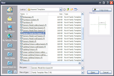
1) Create a new 'Generic Model Line Based' family.
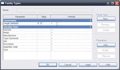
2) Change the "Length" parameter to 8'-0" via the "Family Types..." button.

Just like this...
Good so far...

3) Load a Cabinet. (If you don't already know, this is what is called nesting a family. I like to call them bird families...) -yes that's a (bad) joke!
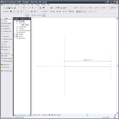
I am using the Double Door & 2 Drawer, as you can see.
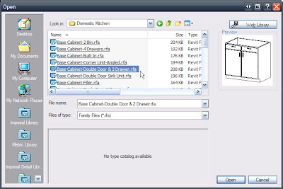

Note how this cabinet comes in at it's default size...we'll be synchronizing and locking that to a parameter later but since we haven't created the parameter yet we'll do some other necessary work first...
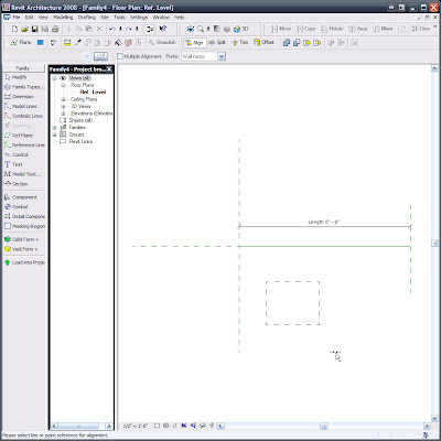

Such as Locking the Cabinet to the Ref Planes. (Note: To get this line based family to work this time I did have to re-do this locking after I constrained the objects to the upcoming parameters, (last time I showed a colleague this it worked fine, without re-locking...It's all about process) so be ready for the family to potentially fight you as you go...Flex every step of the way so it's not too painful.)

Align/Lock to the start:
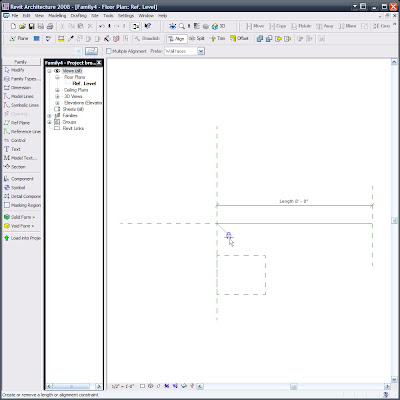

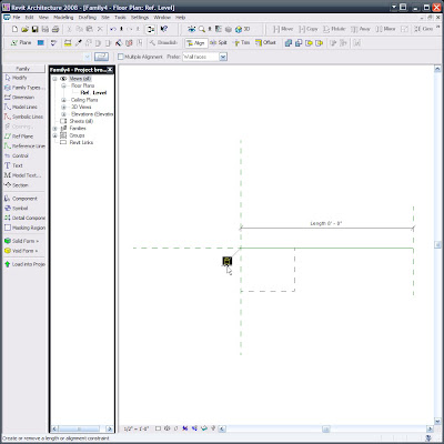
Align/Lock to the insertion point (Yes, the intersection of these Ref Planes is the insertion point, so if you need an offset insertion be aware of that):

Where are now, #4)? I think so...No matter, the next one may seem odd no matter the number.
Array the cabinet 3 times; constrained, grouped & associated. Then select one of the array group members
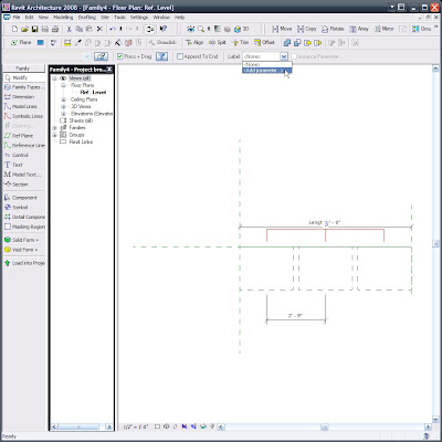
and select the Array Control Line, (the odd part is the Array Control Line disappears when you're able to select it) add the parameter "NUMBER OF CABINETS" (similar to the one that follows the next image) and it will then be associated to the array.

Below is an image of the Control Line selected...The oddity is that the Control Line seems to disappear or at least go invisible when hovering over it, so if you want to select it (and we do) and that control line disappears then click there, you are sure to select it since it looks like you can't. Yes that IS what I said. Perhaps at AU I can get an answer from a developer as to why this is the case....

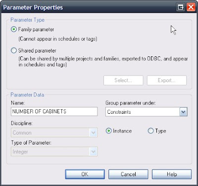
Here's the "NUMBER OF CABINETS parameter's" parameters: (Nice use of the language/lingo -I think)...
5) -Or is it 11?...Anyways, again Via clicking the "Family Types..." button we can and must set up the following additional, necessary Parameters:
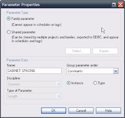
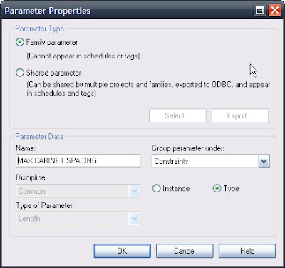

This last parameter I attributed to the dimension below:
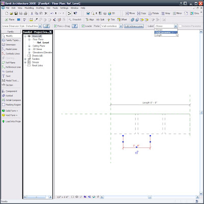

Now, you should know that when I entered the formulas, per the
following image (which you can and really must consider as being the next step!!!) the dimension (shown above) needed to be deleted. I let that happen and didn't question it later on since the family works without it (as long as you don't set the overall length below 6'-0"... yes we could place more constraints via a conditional statement to allow for that but for this particular family I didn't find it necessary to have a multiple, double cabinet be so small...I say let it break in that case, it's just too illogical)

So now make the parameters be the following formulas and values, making sure to hit APPLY after inputting each formula. (Remember formulas ARE case sensitive!!!)
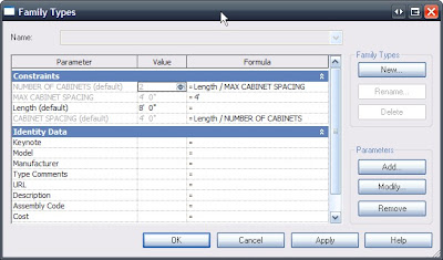

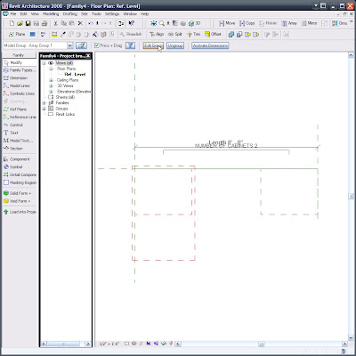
This time while I was creating this line based cabinet family (and after letting the dimension be deleted during the error/warning stage) the middle cabinet disappears...There is actually a good reason for that and I eluded to it earlier, way back in step #3... Even if you don't care to go back and look here is the 'fix'.

Step Whatever): Edit one of the Array Groups and select the cabinet and click the Properties button:

When you get down into it's Type Parameters look for the Width parameter and click the tiny little = (equal) button...(Actually I think Autodesk tried to hide that = button from us :-))
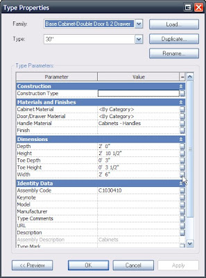

Now set that equivalence of the Length parameter to CABINET SPACING.
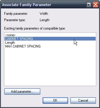

Now everything seems to work brilliantly!!!
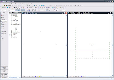

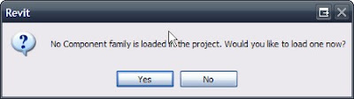
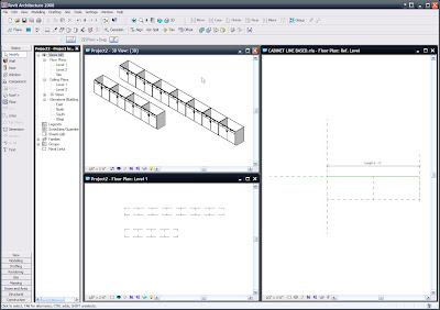
So we can load it into a project and input them via the Component command.

One final note: We may (actually we do!!!) want to go to SETTINGS/FAMILY CATEGORY AND PARAMETERS...:
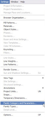
and set (unless we previously set this) Line Based Families' "Family Category to be Casework, like below... But if not we can do it anytime and then reload!!!
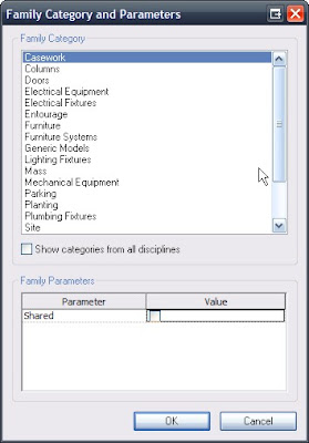
This goes for exposing materials, etc., etc., ...


NOW FOR THAT TRELLIS:

I am only including the text of it since the step-by-step takes about an hour to demonstrate live (with talking :-)) and with screen captures added would take me a lot longer and enough is enough for tonight!!! Also note that the trellis recipe may require some interpretation, since it is purely a copy/paste of my personal notes, for demonstration purposes (By the way, this Demo kicked some ass and opened some eyes at the LA RUG meeting in July where I presented it for the more than 100 Rev-Heads in attendance). The reason that I say all this is that the directions are (mostly) in exact order, yet may possibly be in need of connecting some dots... In any case I hope those directions help and well, I am confident that they will, but if you need help just drop me a comment and I'll help you out further. See you soon!!! -J

1) New Family “Generic Model” (Square Column)

2) Create Shared Parameters: Type, Other (faster for this demo)

a. B Wd (B = Beam, C = Column, etc.)

b. B Ht

c. B Lng

d. C Wd

e. C Dp

f. C Top

3) Create Square Colum

a. Use the 3 shared Parameters: C Wd, C Dp, C Top

4) Create Round Column (Save As ???)

a. Use the 3 shared Parameters and Add:

b. C Rad (Make this equal the following formula)

i. = C Wd / 2

5) Make

a. B Wd =

b. B Ht = C Top+1.5

c. B Lng =

d. C Wd =

e. C Dp =

f. C Top =

6) New Family “Generic Model”

7) Create Beam

a. Use the 3 shared Parameters: B Wd, B Ht, B Lng

8) New Family “Generic Line Based”

a. Make Length 8’-0”

9) Insert Beam Perpendicularly to length line, Place it and Lock.

10) Copy it to the opposite end & Lock.

11) Add & Place Columns

12) Create a ‘Family Types’ Instance Parameter: Column Type and choose Generic Models. (or change column & beam families to their actual category and use those here)

a. Select all columns and set them to have the parameter Column Type.

13) Array 1st beam 2’-0”: Group & Associate, Move to 2nd, Constrain.

a. Select the Arrayed Beam and select the Array Control Line and add a Parameter: “Number of Beams”, Constraints, Instance and OK.

14) Dimension the 1st & 2nd Beams

a. Make it the Parameter “Beam Spacing”, Constraints, Instance and OK.

15) GoTo Family Types and add the following Parameter:

a. “Maximum Beam Spacing” , Constraints, Common, Length, Type OK in this dialog, then APPLY at the next; (Not OK…we want to stay in this dialog for a minute).

16) Make the Parameters the following Formulas:

a. Maximum Beam Spacing = 4’-0”

b. Number of Beams = Length / Maximum Beam Spacing

c. Beam Spacing = Length / Number of Beams

Functional Families Rule!!!