A BIM Junkies Guide to Getting Over an Addiction to Lines..."Toward a Zen of BIM"
Tuesday, May 29, 2007
Color Scheme Legends and True Colors
Ok, post 3 of 3 for today. WOW I was up late last night, going off on idiot computers...Too much BBQ perhaps.
So you say you want to use Pantone (R) colors, or RGB color values for object's surfaces, etc. in Revit (maybe to get a finish color without rendering???) and you want to have the colors actually print correctly (or as near to correct as is possible for your system's hardware)? Well this little trick has been gleaned and can be used to get the output you require, though there may be (is) the need to test the different settings out a few times, to get them "just right"; depending on your printer's calibration (or lack thereof). -Please do small test prints at the final output quality and save a tree (AND your ink!!!)
OK. To begin with (assuming there are already objects that have surface patterns that are set to having a 'solid fill' and said solid fill is set to a color other than black or white!!!) set the following via "Advanced model Graphics" (found where we turn our shadows on) to the following settings:
1) Shaded With Edges (Note: Perhaps it is the case that these views are for inclusion into CD sets: In that case many (or most) other objects will probably NOT want to have colored surfaces for these specialized views...)
2) Cast Shadows checked
3) Sun (between 85% & 99%)
4) Shadows Off (unless you want them on, but this posting is mainly to get colors correct in hidden line views)
Have fun and be sure to share your experiences to forward the expert use of Revit. Also: think long and hard on this one...maybe even talk to the entire team...It may take some management.
Oh, yeah, I left 'Override Silhouettes' out of this exercise since that doesn't affect the colors. But that too can be useful, especially when combined with shall I say, the line work tool and object overrides? Yes, I will... These few things should and will help us to get much richer, more illustrative BIM documents.
-J
Integrated Practices...YAAY, Finally!!! When it actually happens en mass.
Today: 3 posts (this is the second) and it's a pretty good read from our friends at Architectural Record: One of my favorite quotes from it is: "...(BIM) is enabling— some say forcing—this information-sharing, integrated-practice culture to emerge." Click me for the entire article.
OK: So "Today I Picked Flowers"
Well, Not really but this is going to be an 'Ideas Only' posting... While reading a fellow BIM Blogger's thoughts on Technocentrism (Thanks JN) I had these thoughts. I hope they apply, here ' goes:
BIM too will be surpassed one day by something more brilliant...the only constant is that all Architecture and Engineering solutions (at least the great ones, in my opinion) are born out of imagination. The technology available at the time is merely what we'll use to communicate those ideas so they can be paid for and maybe even built.
Now, BIM software may help us in those endeavors but it will not make the ideas for us and although we can program in mathematics, formulas, parameters, etc. to solve problems or even to generate shapes, etc. the computer is still quite dumb (They have no creativity!!! And that's what ALL the Arts take)...
As, I believe, Picasso said of computers: "...But they are useless. They can only give you answers". Any idiot (sorry idiots) can use PhotoShop, etc. to apply a watercolor or impressionist or cubist 'effect' but no computer will ever come up with those movements on their own, let alone in context to society or fractions of societies.
So BIM or CAD or even BIM-VS-CAD should be seen like the pencil overtaking the pen or scratching in the dirt...it's just a new (maybe better...definitely better!!!) but still just a tool; another way to illustrate our dreams so they can be manifest into 'reality', such as it is. It didn't take computers (as far as we know) to design any of the pyramids around the world and look at their impact on civilizations. Nor were GaudÃ's forms realized on computer...it will always be genius (or some close approximation) that generates Art, let alone Art of any great impact. I just hope some of the buildings (and Art) we are now creating don't make us, as a society, look like idiots (sorry again) who are blindly applying an effect or two, or ten... and then thinking that's somehow worth the toilet paper it would be printed on.
Viva la imaginación.
-J
Monday, May 14, 2007
Revit File Sizes: Some ideas...
Bouncing around Augi I found this paragraph (Sans Additions) from the 'Diary of a Revit User: Purge Party - May 2007' article particularly intriguing (see below). As I am putting together a presentation on Revit regarding The Appropriateness of Content (or lack thereof). This presentation will deal with when to place items, when not to, why different approaches get different results, etc. Well as I said the following is kinda interesting:
"...First off, a Revit user must ensure that a minimal understanding of modeling and project file size have been achieved before beginning a Revit project. (No Shit...I couldn't agree more!!!) The user would then understand the implications of developing a model without populating it with unnecessary elements. (Hopefully) Secondly, the user must understand the basic differences between linking information and importing information. (The difference between Playing with and watching!?) Each method is equally important; however, if the model is to be developed so as not to end up being in a position to spring clean, then the proper choices must be made before introducing external information into the project file..." (As it is with everything in life...Good thing we have 'purge' in Revit...I know I could use that in my life from time to time!!!)
Well, That's it for now, the kids need to get to bed, I need to email my hockey team and well, that's enough for now...Work Intelligent (ly)!!!
Wednesday, May 09, 2007
Revit Architecture 2008 2: More on Roofs & Floor Enhancements...Revit Structure Too!!!
Slope to drain...Now we can for real!!! (Unfortunately there is no automatic tag that will report the slopes (yet?)).
Perhaps you recall the tools or maybe not; either way they are found on the Options Bar after you select the Floor or Roof (just to the right of 'edit').
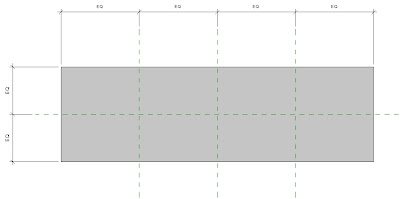
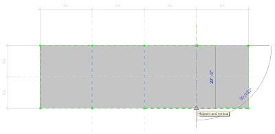
So; below is a 'flat' Roof with a few Ref Planes placed for us to snap the 'split lines' to.After creating a flat roof select it and the new buttons reveal themselves. The next step for this exercise is to delineate the ridges, valleys, etc. for our desired drainage (or just to design a complex object, etc.) for this we use the 'split lines' button.
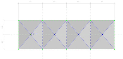
The next two images were taken in the midst of drawing the 'split lines' at each vertical Ref Plane, then corner-to-corner.After we place all the 'split lines' required select the points at the intersections and tap into the number and set it (them) at the appropriate (negative ?) relative height (s), as illustrated above.
If you already hit escape, or need to adjust those points in the future then you can always use the 'modify sub elements' button.
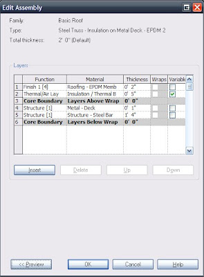
Some of the new parameters added to allow much of this new functionality is set from editing the' structure' of the Floor or Roof elements from their Type Parameters: for this I set the Insulation/Thermal layer to be the 'variable' one; Note that the finish layer above it automatically follows the now variable slopes of that underlaying sub-element.
(That's cool!!!)
Here is what that all looks like in a partial section:
Then in 3D:
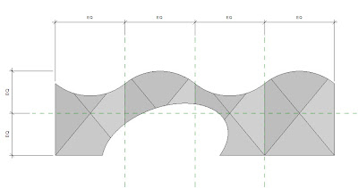
And as promised: To get the (I know, rather unsightly...) shapes below I placed an eliptical shaft opening at one side and created a generic, in place 'void' family and used the cut the geometry tool to give the multiple curves at the other side. Don't worry, we can create beautiful shapes also!!! Although as shapes go (not roofs) this isn't that bad...Now with these new tools and functionalities I estimate there can now be even less lines drawn in our ever increasingly coordinated and BIMalistic (BIMtastic???) projects and world. Next maybe we'll look at the final new tool for roofs and floors...'Pick Supports'...yes we'll place structure for that!
Subscribe to:
Posts (Atom)