Thursday, December 27, 2007

Well I was just pissing off (actually, I hope not) some Augies and have a couple more ideas about BIM-Clouds...

In this post thread: (Yes, click me!!!) W. M. wrote:
...In this thread, make your case for a true "Revit Building" which includes everything needed for documenting a building, and what you'd be willing to pay for it.
Why do you need a unified version of Revit? Discuss...

I replied...
W,
Great Idea, it's on a lot of peoples minds and has been for years now. I too used to think endlessly (a bit exaggerated) about the benefits that a unified Revit would be; It is a good idea, but more and more lately I am changing my mind!!! I now feel it would only be a stop gap measure (though a good one). IMO it is also (now) a matter of thinking small.


Don't anyone take that personally, I said I think it's a good idea too...

Do we want one Revit?
Or, better yet,
Would you find it in your businesses interest to be able to use any, and every tool? To be able to interact with a real "central" database, no matter the task, no matter the tool?...Revit, 3DS, Sketchup, Maya, Ecotect, Illustrator, etc. Whatever...and without any data loss. That would be worth 5 grand (or more) and still be a good value!!!

I read, was inspired by (and thus blogged about) a great article on "Google and the wisdom of clouds"
. I have been intrigued at the prospect of going beyond perceived limitations for years and after reading about the clouds and the brilliant folks who came up with that thinking I am in a state of trying to bring that clarity to AEC.

Everything is possible, right? Well, let's think big; and if you already think big then think bigger and if you already think bigger then tell me why aren't you already developing BIM-Clouds??? ;)

Frankly, dreaming of a unified Revit, no matter how much better it would be is still too short-sighted, unless we see it in Revit 2009. If ADSK hasn't done it yet we won't see it (probably) for 3 to 5 years? But if we bring about radical, new ways of thinking and practicing Architecture, etc. our processes can keep from being mired in softwares that never seem to deliver on their initial promise.

We can make huge, positive changes rather quickly: it's called evolution.

We can make small, incremental changes in reaction to things but I think that is called growing old and dying.

I want to evolve our industry, do you???

-J

Sunday, December 23, 2007

Everything is Possible. ...the Wisdom of Clouds

So as I get closer to completing the transcripts for the "Why Can't (some) Designers Model (Design) in Revit" posting I have realized more and more clarity regarding some now core thoughts that I am aligning myself with and developing.

The first is I believe we must think large(r) (No I don't mean out of the box...I don't like using that tired, burned out term ...it's so 2006... also I find it is constricted to a box itself); So I say let's Think Large(r)! (The (r) does not mean that it's registered it eludes to If we are thinking Large; Then IMO: we should be thinking Larger: Otherwise think Larger from the start. Shoot for the furthest reaches of the Multiverse and if we only hit the center of our own Galaxy then work with that but never stop dreaming.

OK, Larger? Yeah; Larger!!! I feel another Revitism coming... In order to focus one must un-focus.

I have seen a lot regarding 'One ("Grand-Unified") Revit' on both AUGI, in User Group discussions, etc.; Shee-oot in the past I have even thought that such a unification would be a great idea and an end in itself... well, I now believe we can get even better than that.

I propose that the One Unified Revit concept is too small. While it may be a great stop-gap measure, I think it would only get us so far.

Do I hear some of you getting pissed off at me again??? Well suspend that for a minute...

Thinking bigger, in regards to this unification and what I suggest is that we strive A Single, Central Database Multiverse. In this workflow there is really one database and many satellite tools, Revit being one (or three) of a multitude that would use the SAME data, no data loss through "interoperability" hindrances, etc. Word, Excel, Photoshop, Illustrator, Maya, 3DS Max, Studio Tools, Sketchup and any of the other tools we use...Now I know that ADSK can, yet may not want to (or be able to???) create interoperable softwares with their competitors tools but why not? License it out and become the BIM (IBM) to a Sketchup (Apple). If one delivers great Designs that are usable, functional, responsible and sustainable, etc. then everyone (mostly) will use it... Kinda like what we (AEC Industry) strives for. If Apple licensed out their shit back in the late 70's/early 80's like IBM did then we'd never need those funny commercials with the MAC & PC dudes. BTW: If you have a sense of humor and like EITHER a MAC or PC based computer then CLICK ME!!! The comments there are great too!!!

If we demand this, then someone would make it, I'm sure. I know it would allow us to create better work and I can surmise that it could propel ADSK to become #1, not #4.

Remember history so we don't have to re-live it. There was once a Berlin Wall, a Roman Empire and if ADSK really delivers that which surpasses the average and really adopt a vision Toward a Zen of BIM (if I may use my own term), giving us tools for solutions, rather than providing us tools and CALLING them solutions; then AEC can become a truly Green Industry. Green and Zen alike must be as complete and holistic as possible with no (or as few) inconsistencies as is possible and as we all know (or should know) Everything is Possible.

Now here is why I am going on and on with (and in) this post: My whole journey; "Toward a Zen of BIM"; is leading me on a path toward 'process enlightenment', if you will, and if you know a thing or two about these types of journeys toward enlightenment you may know that when we're on a path, possibilities present themselves from time to time: this is where the "In order to focus one must un-focus" quote comes into play: we need to stay open so we can see the signs when and as they're presented. If we are overly focused we may miss what's right in front of us.

Sarcasm alert!!! For you Revit users: that last sentence was dually a really good idea when searching for enlightenment and a thinly veiled jab at the fact that error warnings can be so far (bottom right of the screen) from where we are focused (on the cursor) that we don't always see them. Stay aware!!!

I include the following link as an example of one of these signs; it speaks to thinking strategies and ideas and can be extrapolated into being on point with the kind of creative thinking we all could use. I hope that you will be inspired as much as I have been... And that's a lot, so have at it!!! Google and the Wisdom of Clouds

-J
Tuesday, December 18, 2007

Why Can't Designers (Really) Model in Revit ...Yet? 2 -Or can they???

I have gotten a lot of interest regarding this idea from colleagues, friends, participants and others around the BIM-Blogosphere, so I just want to let everyone know that I am compiling the first round of results from the Unplugged session and ask that you (we all) be a little patient.

I am transcribing the audio and compiling that with other notes from that day along with expanded thoughts and comments, so check back in the next week or two and you will be most assuredly entertained, if not enlightened as to where the industry in my opinion needs to and will get!!! With all of our help...

Original Post

Thursday, December 13, 2007

My "Single Central Database" approach & an Homage to "The Six Phases of Revit"

Typical Misconception:
Learning Revit is like Peeling an Onion.

Well let's take a look at that: traditionally we start by peeling away the skin then removing each layer one at a time until we hit the center. All you chefs out there please suspend your thoughts of the other 1000+/- ways there may be to peel an onion, I'm just making a point!!! :-)...Either way I find this analogy doesn't touch on Learning Revit successfully, thus: Misconception.

At a basic level I like to explain that:

Learning Revit Is Like Peeling An Onion From The Inside Out!!!
The Beginning: The Center of the Onion. We begin not knowing anything about Revit and must peel the tiniest part from around us; installing Revit. Then we transition into Phase One and we are impressed. We now have a bit of knowledge and room to grow into since we peeled another layer; "Hmmm I'm not so cramped in here... Moving on within Phase One we can quickly learn that there is another, larger layer surrounding us now and we don't like the perceived limitations (Phase 2), this can truly be like an onion; a bit spicy and can make us cry; that is until we learn to cook with it... Enter Phase 3; thus peeling another layer from limiting us, AKA learning more and learning to use Revit Like Revit!!!

Although the 6 phases are NOT a linear process (you can expect to experience every Phase many times in your Revit life) I will continue in a linear manner herein.

Cruising along in Phase 3 we get confident enough to create a family of our own... Just like adulthood & Worksets, all Family editing and creation in Revit "...takes careful planning and management..." So: Phase 4... What The Fuck is going on here.

The family editor can be a difficult mistress, no matter your level of Revit mastery; it is like a beautiful Lover that knows they're beautiful (and are a bit limited intellectually); Life is great when things are simple, fresh & new but as soon as things get difficult, or you want to do something complex, (or you don't know that your actions are creating unintentional relationships) then things can go bad quick...Remember to flex early, flex often and flex at every step... Also, it's important to know that lovers usually don't like to take on relationships that you may feel are logical (they are not mind readers) and prefer to impose their own relationships and terms on you!!! Whether or not this is true in 'real' life that's for another time but in Revit it does happen. Never fear, you're just about to peel another layer away (or one of a billion) and get to Phase 5.

Whew. Although I, personally, wouldn't call it "conquering" the family editor (if that's even possible): in any case it beats Phase 4 and the WTF-Zone!!!.

Phase 6 is a nice thought but I suggest that's really phase 5.

A zen of Revit, as I see it can not be achieved until there is truly a single model. A single database, wherein no matter the tool you use, no matter the task you need to accomplish, you access information in that "Single Central Database", no matter the format of info you need, without loosing any of the other data. (read as 'True Interoperability').

For instance: In a Single Central Database Universe 3DMax would pull ONLY that info it needs and basically ignore the rest, IES and Ecotect would do likewise, etc... That is why I speak of (and am beginning a book) "Toward a Zen of BIM".

Enlightened states are bigger than any one tool and we must think creatively and honestly and in universal terms.

As I see it, for BIM to be Zen-like, in a completely coordinated and efficient manner it must embrace the "Single Central Database" approach. The more this is endeavored toward the closer to Industry Enlightenment we will become, thus we'll earn more $ as well as gain real sustainability, not payola-realized-sustainable projects, as we can find examples of today.

So without further ado, I repost a copy of Chris Zoog's oft-cited "Six Phases of Revit" s
o I can not only have easy access to it when doing training, etc., but it is helpful in furthering many conversations and ideas I am interested in and am exploring.

Six Phases of Revit Copyright 2003 Chris Zoog

Phase One - Initial Excitement!!!
"Holy Crap! Look what I can do with this thing!"

Phase Two - First bump
"Hmmmm...? Why won't it do what I want? That's not how I do it in (insert other cad software here)!"

Phase Three - Creamy Middle
mmm... things are going more smoothly, now......mmmmm"

Phase Four - WTF stage
The family editor "eats you up and spits you out"!

Phase Five - The Enlightenment
Things really begin to click! You understand why things are happening in your model, and better yet how to control them and avoid problems. You have conquered the family editor.

Phase Six - Zen of Revit
You have mastered nearly all things Revit. You "know" what Revit "likes", and what it "dislikes" during model construction, a sixth sense, really. You spend your time exploring and tweaking advanced scheduling, OBDC, external parameters, AR3. You have a template to beat all templates, families for every situation. Copyright 2003 Chris Zoog

Wednesday, November 21, 2007

Browser Organization: Some Ideas

Do you need to break up your browser organization beyond the few options given Out-Of The Box in Revit? Well then here we go:

1) SETTINGS-PROJECT PARAMETERS-ADD
Then input the following:


That will add a new field to all your View's Properties.

Next Edit one of the existing browser organizations (NOT the "All" one though)
Be sure to Duplicate the one before editing!!!


This is where you'd Duplicate the Type you chose...I renamed mine VIEW TYPES, just like the parameter...are you getting the idea there's a method to this madness???

Click the Edit button next to Folders (you can mess with filters another time, we do not want any filters on this setup)


Set the following...


Now choose the new Organization Type from the Type Selector...
Oh SHIT!!! What are those ???'s...Never fear we just need to input the values for our new parameter, for every view...


Select the views you want to categorize, hit the Properties button and input a value in the VIEW TYPES field... I am using WORKING VIEWS AND SHEET VIEWS, but the possibilities are endless (and this is but one simple example on how to mess up your Revit project...uhhh...I mean help you streamline your project)...I say mess up because we must communicate to the team that we did this or they'll create views and not put a value to it and the ???'s will come back!!!

Voilà as we add a ton of views we can keep things straight, like having J's Views all list together!!! ETC., ETC...


Thursday, November 15, 2007

Ready to be floored? Strategies and Ideas

I will add to this post later Thursday evening, so you can see what I'm talking about...rather what I will be talking about!!! Ready to be floored? ...I guess it's Thursday evening already!!!

OK here we go: a colleague asked about raised floors and we had a nice conversation about what to model, when and some options for floors that are raised above the level. The above examples illustrated some of the choices we have in Revit; shy of modeling (what we found later to be a raised computer room type of floor).

Floors on "Level 02, from the left:
1) 2 seperate floors; one as a 'finish' floor, one as a 'structure' floor. This lends flexibility for multiple finishes per room (or parts thereof) without using the split surfaces/paint bucket methods. I think real is often best...after all this is how it'll be built, right?
2) Standard floor (just for reference...a control group of sorts)
3) Same floor as #2 but with an Offset from Level to get the structure materials to top off at the level. (this is what we dimension to & how we construct, right?)

Floors on "Level 01, from the left:
4) Same floor as #2 but with a 1'-0" Offset from Level. (you know a 1'-0" raised floor)
5) one (of a million+) type of raised floor assemblies. (minus the extra pieces for the computer floor below. Many times, even if I ultimately will need the same floor assembly as below I will use a more generic or schematic approach, especially before Design Development...then perhaps later in the project's development will we want to employ a floor more fully modeled...especially, especially, especially if we haven't made a bunch of $$$ yet.

Hey, another Revitism (or is it an Architecturalism?) Model what you need When you need it, not a moment before.

So you say you are in DD and really feel it necessary to model it up? I hope your project isn't too large...or at least the amount of this floorisn't; If it is a large area and a large project don't say I didn't warn you not to!!! But if you use this make each piece as separate components and nest them into an assembly just watch for the pitfalls of having pieces overlapping...can you say 'yes/no' visibility parameters for the legs???

A few questions in regards to this type of model:
a) What happens when the size of the room doesn't exactly fit equal size panels?
b) What happens when the room isn't rectangular?

Yes, I know we can model those odd sized/shaped panels but you can see there may become extra work created by trying to model too much...remember be mindful of the project specifics...I know you will!!!

The following is an image of a nice family (I like nice families!!!) a fellow Revit Monster created for just such times; but I'll warn you that it requires careful considerations before using, such as project scale and the benefits of having all the extra 3D pieces all around the model. It can be useful for easier sections and details but again the appropriateness of this will vary project to project. Don't forget to model the components with symbolic lines to keep the 3D clutter down...


(thanks to John C. Raiten for the family image)

Wednesday, November 14, 2007

Equal Dimensions on Both ends of a Dimension String??? Fuck Yeah!!!

Have you ever wanted a dimension string to have EQ. on each end of a string? Well, when those values are actually equal and you use Revit you can get it...How? I'm not saying...but I will say that our best friend (in Revit) can be the Right-Click...perhaps you see where I am going with this?

Frankly we should always have a sense of curiosity and rt-click and search the object properties... You never know what you can find until you find it!!! -Ohhh Yaay another Revitism...

OK, I will tell you after all: (obviously)...


1) Dimension the objects
2) Right click the dimension string and select EQ. Display

3) Run around the office yelling "Oh fuck yeah!!!"


Now there are limitations: it will only report EQ when either all objects are equal or the 2 opposing ends are equal. I have found no other occasions where this works, but that won't stop me from trying; It was just a few months back that I did that (used my curiosity and ignored what I 'thought' I previously "learned" or "knew") and stumbled into finding that Elevation Views can now be Duplicated, when they weren't previously (and oddly enough I never saw official documentation...hmmm)... Just watch out for the duplicated elevation markers hiding in the same location as the original ones!!!

Tuesday, November 13, 2007

Why Can't Designers (Really) Model in Revit ...Yet?

Are you going to Autodesk University 2007? (AKA: AU or AKA: THE gambling & drunkfest...Uhhh I mean...a great place to learn and network). If so on Thursday November 29th 4:30 to 5:20+ pm, the Titian Room 2203 of the Venetian Hotel, Las Vegas, Nevada, USA, Earth, Milky Way... is where you want to be.

We will be Un-Conferencing and spouting off (politely discussing limitations and solutions as we see them) to ADSK; in regards to Revit's modeling capabilities, or lack thereof. I have the intention to become a positive force to affect change in how ADSK responds to industry needs and Revit's better-ization is a great place to start!!! If you are passionate about this (or just want to have a great discussion) then COME ON DOWN... If you can't make it there, then I invite you to add your comments to this post and I assure you that all good ideas will be brought up and discussed.

I will be creating a list of participants, who want to sign on to have the development teams (actually the product management teams as well) at ADSK hear our requests and finally act on them...

I'll also be creating a comprehensive list of all of the modeling tools, workflows and flexibilities that are required of a BIM software (but obviously and specifically Revit!!!); that is to be used in the production (let alone documentation) of the multiple disciplines & building types within Architecture.

Architects, Engineers and everyone else who show up in Vegas plus everyone who contacts me herein is invited to add to the discourse, so speak up, be heard and
transformation your own voice into a force for industry change, in your pursuit of true BIM projects.

Without further ado; here's the info on the session I will be leading:


Thursday November 29th 4:30 to 5:20+ pm, the Titian Room 2203 of the Venetian Hotel, Las Vegas


Why Can't Designers (Really) Model in Revit ...Yet?
(And NO!, it's not because Designers can't model in Revit: rather, it's because Revit Can't Model in Revit!!!)

Compound curves, lofts, parametric shape studies and manipulation; interactive/flexible shape editing...They are not available in Revit (or are barely developed); so, how can we get them there to the degree that we all dream* (*read as need)?


I think it is disastrous that these types of capabilities are not in Revit. This oversight in the development of Revit's modeling is making room for other programs to get huge footholds with designers everywhere. Since these capabilities are present in many software applications, and we all know about them...Rhino, Sketchup, Blender, even Microstation has generative components... Sh*@# even AutoCAD has a loft tool!!!


Not being able to model shapes comprehensively, for real and in Revit makes Architects (yes, MAKES us) use tools such as Sketchup. Sad but true.


Every Architecture firm, whether large or small, need complete modeling tools and ADSK & the Revit Development teams should respond to these needs! ASAP.


Join me in becoming a positive force toward transforming this oversight into a victory for BIM, Architecture, our practices and even ADSK, if they follow through...


Let's see if we can help it be realized, that there will be complete and comprehensive modeling tools & capabilities inside of Revit.

This and more will be explored and discussed so bring your lists and have fun!!!

I know I will...

Wednesday, October 31, 2007

More with: Filters, Fire Ratings & Graphic Overrides

So it seems I failed to give a huge payoff to productivity when using these filters and overrides... VIEW TEMPLATES ...

If you followed the instructions on creating
Filters, Fire Ratings & Graphic Overrides then you may have been horrified when you attempted to place these overrides on your other (insert number here) views that need the exact same look...

Well you'd only be horrified if you didn't think of (or remember, or know) that we can use View Templates to propagate these filters & overrides to multiple views... We can!!!

Just Right-Click the view that has the filters and graphic overrides already applied (in the Project Browser) then select Create View Template From View... Once created you can select any & every view necessary and again Right-Click them and this time choose Apply View Template...
sit back and let Revit do just that!!! (Insert superlative here)


I love when Revit works for me!!!


Wednesday, October 24, 2007

Filters, Fire Ratings & Graphic Overrides

So you want to be a Rock n Roll Star?... Uhh wait... Oh yeah, you want to create fire rated walls in Revit and have them represent visually.... There are many options (OK, a few): One is to use a 'coarse scale fill pattern' and use a hatch pattern (that we usually have laying around from WhateverCAD). This is workable if: 1) You only need them to represent in Coarse views and 2) You only use straight walls, no curves. Not a complete solution and not my choice of them.

My choice is once again to Use Revit Like Revit; thus we will leverage Filters and Graphic Overrides to get this job done to some duplicated Object Types (or do you have them created already?) ...Hmmm...Maybe these should be built into my Project Templates, as well...

In either case we endeavor to Graphically represent our Walls' Fire Rating.

Make any (and every?) distinct Wall Type, for each Fire Rating condition you have (at least at this time): Apply or change your walls to those types, as needed in the project (obviously).

This image illustrates my wall being selected to change it into a 2HR rated wall...


The Wall Type change in action!!! Not so hard, just rename the Duplicate Type and then make the actual addition to the Fire Rating Parameter Value…Yes, I did this for the 1HR wall too...


Now here’s the fun part: type VG (or if you’re me VV…no, this isn’t a W, it’s two V’s)… Click over to the Filters tab and then (gently) hit the “Edit/New” button... As it says “All document filters are defined and modified here”.

BTW: The HERE it speaks of (and will basically bring you) is SETTINGS / FILTERS...


Next, click the “New” button... it's the one that looks like a “green + over paper” symbol…to make your new filters...


Naming them appropriately for the job they are about to accomplish is of paramount importance.


Then equally (yes, a bit of a pun intended) important is making these filters actually filter the correct parameters and that they ‘equal’ (payoff) the correct value you are to ultimately input in the object’s properties (or in our case the values we already put in our Wall Types). FYI: I also assigned these filters to the “Doors” category…and so can you.


After completing the Filter Creation we can apply them to the view and give the actual Graphic Overrides to the distinctly rated walls...Yes, these filter applications are view-specific!!! So don’t forget to apply them to all the other necessary views you may have...


The next two images below are showing the fundamental Overrides that will give the rated walls their look(s)…I know you won’t forget to override both Projection Lines AND Cut Lines…right??? Right!!!


It always helps to have these line styles predefined so they’re available!!! Perhaps 1HR, 2HR, 3HR, 4HR?


And then...

Ta-Da!!!

Oh and If you didn't realize it yet, you can put a Cut Pattern override as well, so if you have some old
(or new) hatch patterns you can use them here as well, just keep in mind that if they consist of thousands of tiny lines there may be a dramatic productivity hit...Kind of "Not-Revit like" if that's the case; but you be the judge...as always.

-J
Saturday, October 13, 2007

Slanted Volumes...I guess the Ramp tool isn't enough?

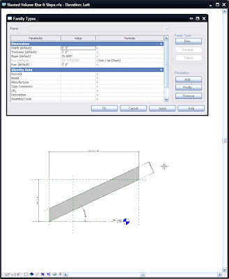
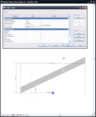
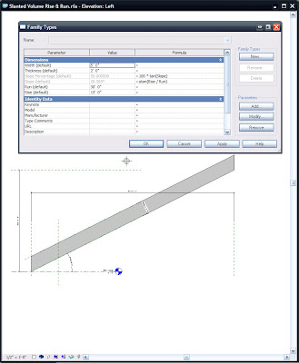
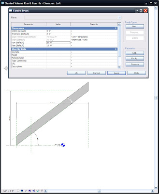
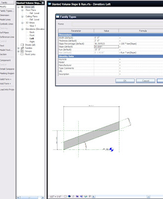
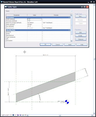
I've been asked several times in the past few months to create (or show others how to create) Parametric Slanted Volumes. It seems that each time the people wanted to input & Constrain using different values: Well, here are 3 variations of such volumes, including the formulas necessary for their manipulation...(Also included in #'s 2 & 3 are a numerical Parameter that gives the Percentage of the Slope).

1: Control Parameters:
Rise & Slope; Run is derived from them.
2: Control Parameters:
Rise & Run; Slope is derived from them.
3: Control Parameters:
Slope & Run; Rise is derived from them.

Nice!!!

First off use my Revitism: Think Twice and Place Once here...Do these parameters want to be Instance or Type? It's extremely important to choose wisely as changes to the parameters later on may create headaches...(if you use shared parameters, needing to change them later most assuredly will create nightmares (for real))

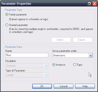
For these families I used Family Parameters (similar to the image below), all set to Instance and grouped under Dimension...


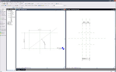
First, as with all Family Creation I made Reference Planes, Parameterized them, Flexed them at every new parameter and when they were all verified (and only then) did I create the solid geometry; locked to the Ref Planes.

So here are the parameters that are the basis for all three families: Rise, Run, Slope & Width.


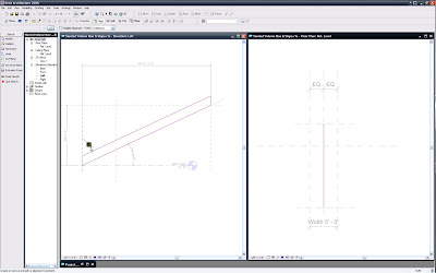
Now that I've flexed and see that they work correctly I'll create a solid extrusion. I find it best to lock the extrusion Sketch Lines to the Ref Planes in this sketch mode; just be sure not to 'mix-and-match' lock locations if you lock the sketch lines lock all of them in this mode, don't lock some sketch lines here and other parts of the solid when back in the family editor,
in relation to the profile in this case, as you'll probably break the family...


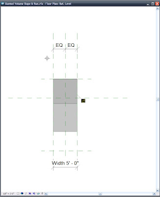
Be sure to use the Align tool and lock the solid to both Ref Planes, that are expressing the Width of the family... (This is OK here and does not constitute a mixing-and-matching of constraints)

OK!!! So now the foundation is set and we're off to the races.

By using the Family Types tool set the parameters as such:

1) When
Rise & Slope are the controlling Parameters, meant to drive the object use the formula: Run=Rise/tan(Slope)...remember to be case sensitive!!!


Here's a flex to test
Rise & Slope...

FILE>SAVEAS>whatever name you like.rfa

Do another immediate SaveAs and rename appropriately for the
Rise & Run variation...
Then:
2) When
Rise & Run are the controlling Parameters, meant to drive the object use the formula: Slope=atan(Rise/Run).

Here is where I added the Parameter Slope Percentage, as a Number, Instance, Family Parameter...That formula is:
Slope Percentage=100*tan(Slope)


A flexing of
Rise & Run, to ensure wholesome goodness. -Buttering the bread, as it were...


FILE>SAVEAS>
whatever other name you like.rfa

3) When
Slope & Run are the controlling Parameters, meant to drive the object use the formula: Rise=Run*sin(Slope).

The Parameter Slope Percentage remains as is:
Slope Percentage=100*tan(Slope)


Here's a flex to test
Slope & Run... Got sandwich meat? hee hee he said meat...(Props to Beavis...or was that butthead?)

If you'd like to know what all the expressions are that Revit finds acceptable for use in Formulas go to that button...oh what was that called....umm....ohh....oh yeah:
HELP...there is a great list there...

So all is good now in the Basic slanted object world (when the Ramp tool doesn't want to be used)...Now to throw a wrench into your worlds: Why not create a Railing (and all necessary Profiles) and use that for your Conveyor System???

Que Evil Laugh!!!

Mmmmmwwwwwwaaaaaahhhhhhaaaaaahhhhhhaaaaaa........

Wednesday, October 03, 2007

Think twice and place once: Section Marker Control and other Revitisms

So here's the down-low on Section Markers turning off at certain scales; along with a Revitism that's useful for most everything: "Think twice and place once"

Ooooh, I like that -even though it is bastardized from "measure twice and cut once"

Anyways: The 'on and off-ed-ness' of these Section markers is controlled by the Hide at Scales Coarser Than property.
And:
The Hide at Scales Coarser Than property defaults to the scale value of the view where you placed the section. Right??? Right!!! And if used mindfully can really make this functionality unbeatable!!! That's where the "Think twice and place once" comes into play. (as with most things in Revit!!!)

If you want the section marker to be visible in views with scales 1/8"=1'-0" and larger (1/4"=1'-0", etc.) then place the sections in a 1/8"=1'-0" view and they (the section markers) will show in views of all scales down to 1/8"=1'-0" but not smaller (or "coarser than" 1/8"=1'-0"; such as 1/16"=1'-0", etc.).

As I said before, the scale of the view where the Section is placed becomes the default value to be found next to Hide at Scales Coarser Than in the properties (see above image), for each section marker... So when working on a project try to (do) keep this in mind since these are instance parameters... so placing a shit-load of sections with an undesired Hide at Scales Coarser Than value can make extra work for...ummm...you???...or those interns (if we can force (i mean convince...I mean ask) them to fix this for us).

Hey J, Can we have Building Sections turn off below 1/8"=1'-0" and Wall Sections turn off below 1/4"=1'-0" just by changing views, or better yet, just by changing the scale of the view we're in?


Yes!!!
Oh, and does this apply to Elevation markers as well??? What do you think???

...I love asking myself 3rd person questions...

BTW: sorry (again) to all the interns, but think of it at this as if it's going to help you out...

So to recap:
1) "Use Revit Like Revit"
2) "Think Twice and Place Once"

Let's see where these Revitisms go!!!

P.S. Has anyone noticed that we can now "Duplicate" Elevation Views??? Sneaky ADSK!!! I like it though...

Good times,
-J
Have You Been Overridden...Again?

Yes I wish there was a Clear Overrides button that would give a list of all objects in a view that have been overridden, along with the obligatory check box where I could reset (or not) those overrides....Especially on multiple person teams when; who knows who does what, when.

Nonetheless:

If there are view specific overrides on objects and you need them to go away, so the representation of the object(s) become default (again) then here you go:


I'll illustrate the Un-Overriding of the wall object...

Select the object/Right Click/Override Graphics in View/By Category

Click the appropriate button: In this case it's the Cut Pattern for said walls...

Next: Clear Overrides.

After you "OK" yourself all the way out it will be back to default.

Have fun...


Wednesday, September 12, 2007

CAD FILES IN REVIT: ON OR OFF THIS VIEW OR THAT

Well I must set my views on BAD CAD data aside because sometimes we need to use CAD files in our Revit projects Especially for Site Plans.

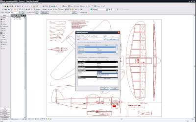
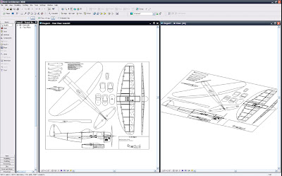
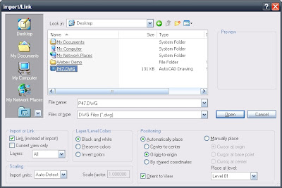
Here's a great way to get functionality beyond the either/or option given when we Link CAD files in Revit. By default there are 2 options to link a file; either into the "Current View Only" or by un-checking "Current View Only" thus showing the CAD file in EVERY view...Sections, Elevations, etc. (Yuck). There's no trick to get the flexibility we want, we just need to do some creative thinking...in a nutshell: Link the file as visible in every view then place that linked CAD file in a workset that is by default off in every view...Hmmm I like it!!!

1) Link the CAD file so it will be on in every view (by clearing the check box as below):


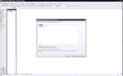
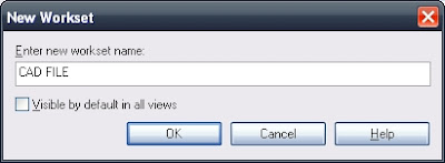
  • Next create a workset (even if you are the only person to work on the project). See the next 2 images...


  • Be sure to un-check the "Visible By Default in Every View" box.


  • Next select the instance of the CAD file and go to it's Element Properties and place it in the workset designed for it.

Yes, the CAD file will disappear initially...do you know why?...Remember? It's workset is off (by default in every view)...No fear
  • Go to Visibility Graphic Overrides (V V or V G) and click into the worksets tab and turn the workset on. This will be true for any view that has a view range that will see the level that you placed the cad link on...Yes that was also a choice when linking, but never fear (still); if you placed the link on the incorrect Level just change that from it's Properties as well...

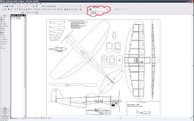
  • Now we have the power to view the CAD file in (as I said) any view that can see it's level and that has that workset turned on...and assuming there is no view specific element hiding of the CAD file...

V O I L A

BTW: If you do an internet search for free CAD plans you may find this great library of airplane (model?) files like the one I used...It's more fun to have fun, rather than blog this using an actual Site or Survey file...also I don't need the litigation...

L8R
-J

Thursday, August 23, 2007

Did You Get The New Revit Build...Yet? 20070810 is Out!!!

Looks like I missed the new Revit 2008 Build a week or two ago (20070810 1700), how about you? Well now we can all have it!!!

What it does:
RAC2008 SP2 List.pdf

Where to get it:
Right About Here.

Now make some more families!!!

Wednesday, August 22, 2007

Do Not Use Internet Explorer. But do use Revit like Revit!!!

In addition to potentially allowing every hacker into our computers, internet explorer (IE) may not show you text properly in some of my posts.

Today a colleague was reviewing how to apply the line based family concept with me and I noticed the text parts of the trellis steps, in the last post had all sorts of formatting oddities (yes he was using IE...though I didn't get the version).

Needless to say that leaves the content (next to) unusable for him and I guess others (sorry for that but you have to call Bill Gates out on that one). I will try to format my copy/paste differently into the future, but if you use IE don't blame me if you can't read my text or get a back door worm from Paris or Britney...

To quote cOmrade, the hacker who got into The Pentagon and NASA systems, from an August 21, 2007 issue of PC Magazine ..."Oh--and don't use internet explorer."

Shit, I heard that loud and clear years ago, that's why I never checked to see if this Blog looks OK in IE...Firefox blows it away!!! One word: DownThemAll!!!

I know cOmrade isn't the first and won't be the last to illustrate the shortcomings of IE, but I think you get my point...

Thursday, August 09, 2007

Line Based Families 1: Kitchen Cabinets...OK, OK And a Trellis...

Firstly: these concepts and (maybe) all family methods can be transposed to many, many other families; at times exactly, at times similarly, at times just in spirit.

Consider, Plan, Think, Re-Consider, Re-Think, then Create.

Consider (what you want), Plan (the parametric needs), Think (about what is needed NOW... Remember you can always make the family progressively more complex), Re-Consider (how complex it needs to be), Re-Think (the final output needs...don't put in any more than you need but no less either), then Create (the best family you can). Also mix-in a conversation with others...this always helps prove or disprove perceived concepts and usually saves overall project time.

The Cabinet family we are about to create (well similar parameters to this, at least) can be used for many other families, one of which I will include a step-by-step of (in text format). It will be the main portions of a trellis.

More about the Trellis following the Cabinet below, so on with the Cabinet sheooow...(Yeah, I was watching a repeat of Elvis on the Ed Sullivan Show...sorry for that rhyme, etc.)

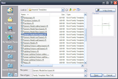
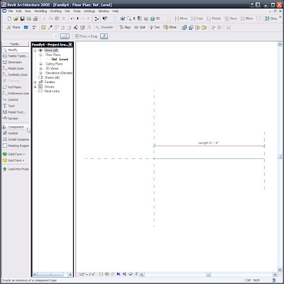
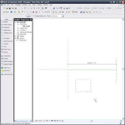
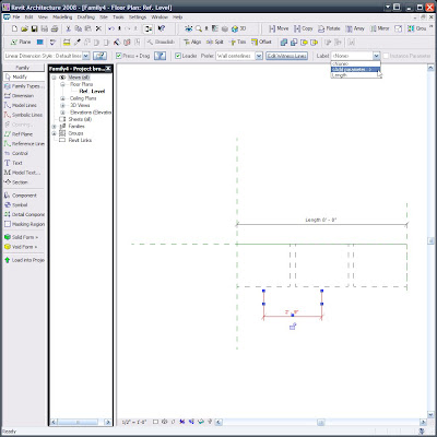
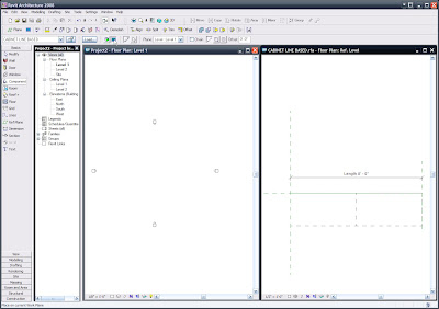
1) Create a new 'Generic Model Line Based' family.
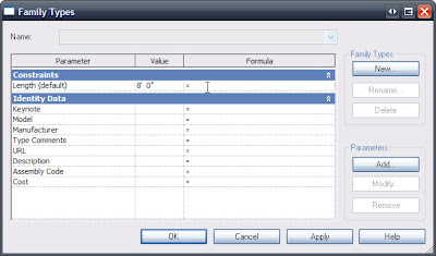
2) Change the "Length" parameter to 8'-0" via the "Family Types..." button.

Just like this...
Good so far...

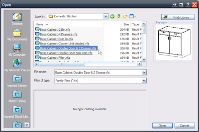
3) Load a Cabinet. (If you don't already know, this is what is called nesting a family. I like to call them bird families...) -yes that's a (bad) joke!

I am using the Double Door & 2 Drawer, as you can see.


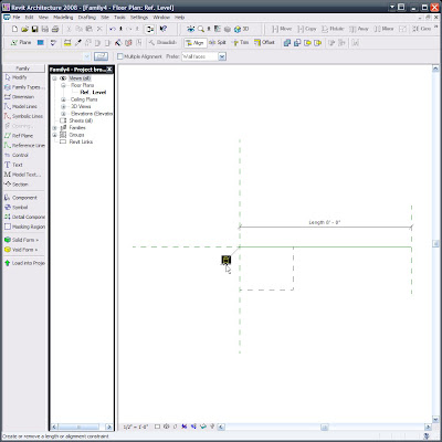
Note how this cabinet comes in at it's default size...we'll be synchronizing and locking that to a parameter later but since we haven't created the parameter yet we'll do some other necessary work first...


Such as Locking the Cabinet to the Ref Planes. (Note: To get this line based family to work this time I did have to re-do this locking after I constrained the objects to the upcoming parameters, (last time I showed a colleague this it worked fine, without re-locking...It's all about process) so be ready for the family to potentially fight you as you go...Flex every step of the way so it's not too painful.)

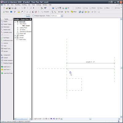
Align/Lock to the start:


Align/Lock to the insertion point (Yes, the intersection of these Ref Planes is the insertion point, so if you need an offset insertion be aware of that):


Where are now, #4)? I think so...No matter, the next one may seem odd no matter the number.
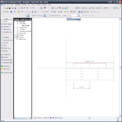
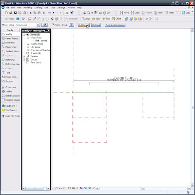
Array the cabinet 3 times; constrained, grouped & associated. Then select one of the array group members
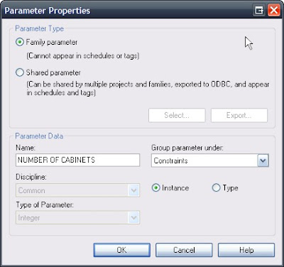
and select the Array Control Line, (the odd part is the Array Control Line disappears when you're able to select it) add the parameter "NUMBER OF CABINETS" (similar to the one that follows the next image) and it will then be associated to the array.

Below is an image of the Control Line selected...The oddity is that the Control Line seems to disappear or at least go invisible when hovering over it, so if you want to select it (and we do) and that control line disappears then click there, you are sure to select it since it looks like you can't. Yes that IS what I said. Perhaps at AU I can get an answer from a developer as to why this is the case....


Here's the "NUMBER OF CABINETS parameter's" parameters: (Nice use of the language/lingo -I think)...

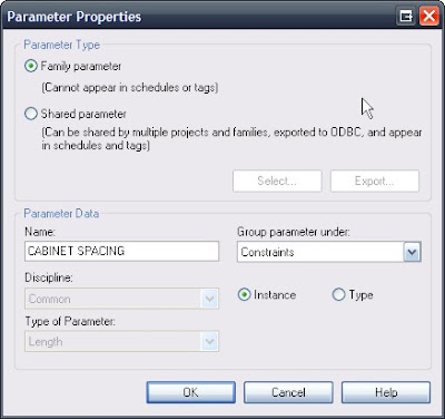
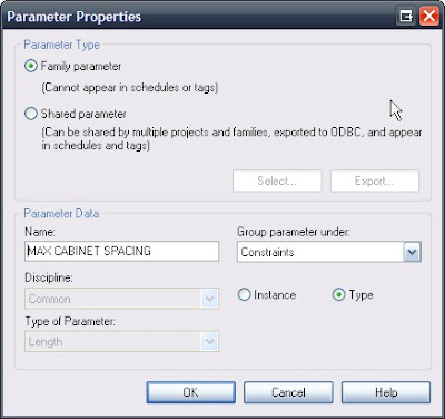
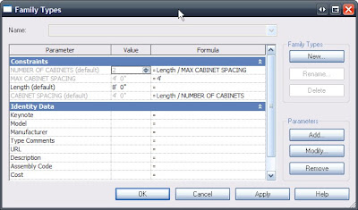
5) -Or is it 11?...Anyways, again Via clicking the "Family Types..." button we can and must set up the following additional, necessary Parameters:


This last parameter I attributed to the dimension below:


Now, you should know that when I entered the formulas, per the
following image (which you can and really must consider as being the next step!!!) the dimension (shown above) needed to be deleted. I let that happen and didn't question it later on since the family works without it (as long as you don't set the overall length below 6'-0"... yes we could place more constraints via a conditional statement to allow for that but for this particular family I didn't find it necessary to have a multiple, double cabinet be so small...I say let it break in that case, it's just too illogical)

So now make the parameters be the following formulas and values, making sure to hit APPLY after inputting each formula. (Remember formulas ARE case sensitive!!!)


This time while I was creating this line based cabinet family (and after letting the dimension be deleted during the error/warning stage) the middle cabinet disappears...There is actually a good reason for that and I eluded to it earlier, way back in step #3... Even if you don't care to go back and look here is the 'fix'.

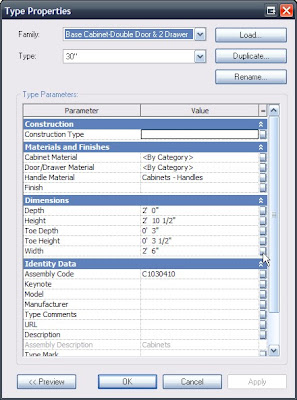
Step Whatever): Edit one of the Array Groups and select the cabinet and click the Properties button:


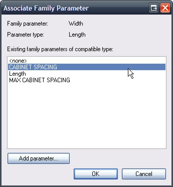
When you get down into it's Type Parameters look for the Width parameter and click the tiny little = (equal) button...(Actually I think Autodesk tried to hide that = button from us :-))


Now set that equivalence of the Length parameter to CABINET SPACING.


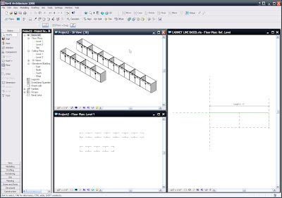
Now everything seems to work brilliantly!!!


So we can load it into a project and input them via the Component command.


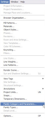
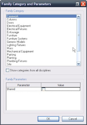
One final note: We may (actually we do!!!) want to go to SETTINGS/FAMILY CATEGORY AND PARAMETERS...:

and set (unless we previously set this) Line Based Families' "Family Category to be Casework, like below... But if not we can do it anytime and then reload!!!

This goes for exposing materials, etc., etc., ...


NOW FOR THAT TRELLIS:

I am only including the text of it since the step-by-step takes about an hour to demonstrate live (with talking :-)) and with screen captures added would take me a lot longer and enough is enough for tonight!!! Also note that the trellis recipe may require some interpretation, since it is purely a copy/paste of my personal notes, for demonstration purposes (By the way, this Demo kicked some ass and opened some eyes at the LA RUG meeting in July where I presented it for the more than 100 Rev-Heads in attendance). The reason that I say all this is that the directions are (mostly) in exact order, yet may possibly be in need of connecting some dots... In any case I hope those directions help and well, I am confident that they will, but if you need help just drop me a comment and I'll help you out further. See you soon!!! -J

1) New Family “Generic Model” (Square Column)

2) Create Shared Parameters: Type, Other (faster for this demo)

a. B Wd (B = Beam, C = Column, etc.)

b. B Ht

c. B Lng

d. C Wd

e. C Dp

f. C Top

3) Create Square Colum

a. Use the 3 shared Parameters: C Wd, C Dp, C Top

4) Create Round Column (Save As ???)

a. Use the 3 shared Parameters and Add:

b. C Rad (Make this equal the following formula)

i. = C Wd / 2

5) Make

a. B Wd =

b. B Ht = C Top+1.5

c. B Lng =

d. C Wd =

e. C Dp =

f. C Top =

6) New Family “Generic Model”

7) Create Beam

a. Use the 3 shared Parameters: B Wd, B Ht, B Lng

8) New Family “Generic Line Based”

a. Make Length 8’-0”

9) Insert Beam Perpendicularly to length line, Place it and Lock.

10) Copy it to the opposite end & Lock.

11) Add & Place Columns

12) Create a ‘Family Types’ Instance Parameter: Column Type and choose Generic Models. (or change column & beam families to their actual category and use those here)

a. Select all columns and set them to have the parameter Column Type.

13) Array 1st beam 2’-0”: Group & Associate, Move to 2nd, Constrain.

a. Select the Arrayed Beam and select the Array Control Line and add a Parameter: “Number of Beams”, Constraints, Instance and OK.

14) Dimension the 1st & 2nd Beams

a. Make it the Parameter “Beam Spacing”, Constraints, Instance and OK.

15) GoTo Family Types and add the following Parameter:

a. “Maximum Beam Spacing” , Constraints, Common, Length, Type OK in this dialog, then APPLY at the next; (Not OK…we want to stay in this dialog for a minute).

16) Make the Parameters the following Formulas:

a. Maximum Beam Spacing = 4’-0”

b. Number of Beams = Length / Maximum Beam Spacing

c. Beam Spacing = Length / Number of Beams

Functional Families Rule!!!