At a recent (last night if you are reading this on the day of the posting) LARUG Meeting Cody Nowak presented a little tutorial on how to hook up Revit with your favorite RSS feeds. I trust you will use this for purely business purposes ;-)
If you'd like to keep in touch with said LARUG just check out and friend us up or follow us using these Twitter and Facebook pages and don't forget the LinkedIn page... Friends Rule!!! Communication Rules too...
BTW: If you can't download the PDF from Scribd use This Link.
C Nowak's Revit RSS How To
Download at will...
Thursday, October 21, 2010


Thursday, October 14, 2010
Are Revit Elevation Views Leaving You Flat? Another How-To-Solve-It with Filters
I want something like this:

HTF can we easily get Elevations (Sections, etc.???) to have distinctions in their graphic representations as they fall further into the distance from our picture plane? You know, get items to appear as if they are fading away or appearing lighter, the greater the distance away they are... without using cruel workarounds like the less than optimal ‘Linework’ tool (read ‘Linework tool’ as the “waste(r) of time and I will probably be forced to rework these over and over as the project progresses” tool) or the shunned Drafting Lines themselves (Please say you don’t use lines). SO how do we??? Hmmmm…
OK, you are about to get the answer to those questions and get one main Best Practice and another one or two solutions that are a less recommended due to their major documentation limitations. Therefore soon you’ll be able to say goodbye to the “flat, dead, fugly, OOTB elevation problem”. YAAY!!!
Although I have heard a lot of comments and complaints through the years about how dead, flat & frankly fugly looking Elevations and Sections can look in Revit, I think it reflects more on us, rather than solely on Revit (but both have been at fault, if you ask me).
I do not want something like this:
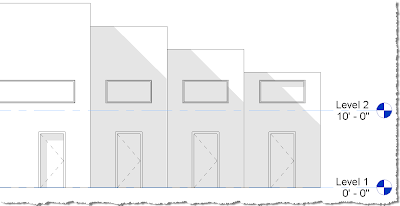 Oh, the reason I say it’s an ‘us’ thing is that there are solutions… If you haven’t found solutions or heard of any (yet) let this be a new beginning; but if you do know of some and one has been to use filters and you have not shared it with the Revit community at-large then I say shame on you!!! Where’s the love??? If you have shared it I could not find it on the weboblogotwitosphere so perhaps marketing needs work?
That diatribe now over, we can continue :) It’s time to buck up partner, there is a really powerful cure (Hint: #2 is the cure I am speaking about).
The two methods we will discuss herein include:
1) The Old School Glass Obstructer Method (See Image 1 below)
Not as recommended as the next method is for a CD set elevations, but useful for presentations and ancillary 3D views/3D elevations, etc.
And finally that Best Practice:
2) The Filter Method (See Image 2 below) Yes. There it is finally, your recommended Best Practice!!!
 (Image 1)
 (Image 2)
These two workflows (if you so choose to use) can also be visually pleasing when used in consort with one another… even though the glass-obstructers need a bit of management via Worksets; just test the output before committing to print the whole set or committing to pronouncing the Glass Method to be your firm’s best practice!!! Look out for the Annotation limitations listed further on, in the step-by-steps for creating The Old School Glass Obstructer Method also; that’s a huge problem with this possible solution.
 (Image 3)
Hybrid Filter-3D Elevation/Glass Obstructer Method –Again, great if you don’t want to annotate the views!!! (Why? See Image 4)
 (Image 4)
If you employ The Old School Glass Obstructer Method (step-by-step below) and think that you want to annotate the 3D “Elevation” views you have a harsh reality coming… You can only use Text. Period.
No Dimensions, no Tags, no Keynotes, no etc…
Why? Because Dimensions, Spot Elevations & Spot Coordinates are only available in 3D views set to a non-flat direction, such as isometric, that’s why. If we look at this logically the flat 3D views only appear flat, thus these tools would probably hit unknown parts of the project, not what we want.
The Old School Glass Obstructer Method Step-by-Step:
1) Create 1” thick walls with a new material that I like to call Glass Obstructer; In the examples herein the material is setup thus (See Image 5)
 (Image 5)
Glass Obstructer Material Settings
2) Place these walls where they need to be (obviously)
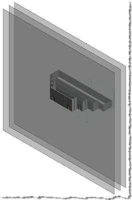 (Image 6)
 (Image 7)
 (Image 8)
Filter Planning Matrix
2) Create Elevations (of course)
3) View Ribbon > Graphics Panel > Filters Tool (See Image 9)
 (Image 9) The Filter Tool
 (Image 10) Filter creation
a. Use the info from your Filter Planning Matrix
BTW: This matrix can be scaled to be useful for any filter plus variants can be used to plan & manage every possible setting in Revit; especially useful since one should NEVER save their old template files into a newer version…Unless you want to lose functionality!!! Really!!!
b. Assign the filters to the appropriate objects; in this case I used only Walls
c. Setup the filter rules
OK get ready: In this scenario I am using an ADSK OOTB template so I simply used the Instance Parameter “Comment” for the assignment portion of this solution… On a real project I suggest that you setup custom/instance/Project Parameters corresponding to each elevation view, for the Objects to be overridden (walls in this case): perhaps they look similar to Image 11 & 12's List of Potential Instance Parameters for Walls to be overridden using the Filter Method:
 (Image 11)
Parameter Setup Example
 (Image 12)
Wall Properties/Parameter value Example
With these setups assign each wall’s instance parameters with the number that corresponds to the (to be) overridden line weight setting (1 for 1, etc.)
Are you with me so far? It is simpler than it appears after a while… Plus very powerful and should open your imagination up to use filters rather than the horrendous Override in View!!!
5) Open one of your elevation views
a. Type VV (Visibility Graphics… Yeah VG works too but I don’t like moving my finger that half inch :))
b. Select into the Filters Tab and Add all of the necessary filters (See Image 13) –That’s right: neither shift, nor Ctrl work here; to select these all just click them individually… *#@! Software Developers can’t seem to make their dialogues work consistently yet… Yikes!!!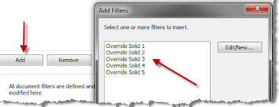 (Image 13)
c. Next, while still in the elevation’s Visibility Graphics Chose the corresponding override Weight for each filter (Projection Lines definitely, Cut Lines ??? Hmmm is that where we’d mess with our sections??? You bet!!!). (See Image 14)
 (Image 14)
Choosing the overrides per filter
d. Click OK and you’re almost there…
I have to take a pause here and admire the strength of filters. Don’t worry, we’re almost Finished!!! (Let's take a look at the (now filter-overridden) View again)
 AHHHHH... That’s a whole lot better!!!
Finally: Oh wow, there's more? Well, yes... we want to push these filters/overrides more methodically than by manually repeating the V/G, filter addition & overriding, don’t we? YES; you had better have said yes!!!
6) Go over to the Project Browser
a. Right-Click the view you just overrode the line weights for
b. Select “Create View Template From View”
c. Name the View Template with a useful name (follow conventions)
d. Un-check all check boxes except “V/G Overrides Filters” (See Image 16)
 (Image 16)
Sweet 16: View Template
7) Apply this View Template to all necessary elevations and if you have set all the walls with the appropriate integer value for those parameters you created you will have similar results as these!!!
Good luck and let us know what great uses you use filters for that may be out of the ordinary.

HTF can we easily get Elevations (Sections, etc.???) to have distinctions in their graphic representations as they fall further into the distance from our picture plane? You know, get items to appear as if they are fading away or appearing lighter, the greater the distance away they are... without using cruel workarounds like the less than optimal ‘Linework’ tool (read ‘Linework tool’ as the “waste(r) of time and I will probably be forced to rework these over and over as the project progresses” tool) or the shunned Drafting Lines themselves (Please say you don’t use lines). SO how do we??? Hmmmm…
OK, you are about to get the answer to those questions and get one main Best Practice and another one or two solutions that are a less recommended due to their major documentation limitations. Therefore soon you’ll be able to say goodbye to the “flat, dead, fugly, OOTB elevation problem”. YAAY!!!
Although I have heard a lot of comments and complaints through the years about how dead, flat & frankly fugly looking Elevations and Sections can look in Revit, I think it reflects more on us, rather than solely on Revit (but both have been at fault, if you ask me).
I do not want something like this:
 Oh, the reason I say it’s an ‘us’ thing is that there are solutions… If you haven’t found solutions or heard of any (yet) let this be a new beginning; but if you do know of some and one has been to use filters and you have not shared it with the Revit community at-large then I say shame on you!!! Where’s the love??? If you have shared it I could not find it on the weboblogotwitosphere so perhaps marketing needs work?
That diatribe now over, we can continue :) It’s time to buck up partner, there is a really powerful cure (Hint: #2 is the cure I am speaking about).
The two methods we will discuss herein include:
1) The Old School Glass Obstructer Method (See Image 1 below)
Not as recommended as the next method is for a CD set elevations, but useful for presentations and ancillary 3D views/3D elevations, etc.
And finally that Best Practice:
2) The Filter Method (See Image 2 below) Yes. There it is finally, your recommended Best Practice!!!
 (Image 1)
 The "Glass Obstructer” Method: Not bad, but perhaps not best either
 (Image 2)
 Filter Method: Best practice (at time of this post at least. :))
These two workflows (if you so choose to use) can also be visually pleasing when used in consort with one another… even though the glass-obstructers need a bit of management via Worksets; just test the output before committing to print the whole set or committing to pronouncing the Glass Method to be your firm’s best practice!!! Look out for the Annotation limitations listed further on, in the step-by-steps for creating The Old School Glass Obstructer Method also; that’s a huge problem with this possible solution.
 (Image 3)
Hybrid Filter-3D Elevation/Glass Obstructer Method –Again, great if you don’t want to annotate the views!!! (Why? See Image 4)
 (Image 4)
Text is the only Annotation available in flat oriented 3D views :-(
If you employ The Old School Glass Obstructer Method (step-by-step below) and think that you want to annotate the 3D “Elevation” views you have a harsh reality coming… You can only use Text. Period.
No Dimensions, no Tags, no Keynotes, no etc…
Why? Because Dimensions, Spot Elevations & Spot Coordinates are only available in 3D views set to a non-flat direction, such as isometric, that’s why. If we look at this logically the flat 3D views only appear flat, thus these tools would probably hit unknown parts of the project, not what we want.
The Old School Glass Obstructer Method Step-by-Step:
1) Create 1” thick walls with a new material that I like to call Glass Obstructer; In the examples herein the material is setup thus (See Image 5)
 (Image 5)
Glass Obstructer Material Settings
2) Place these walls where they need to be (obviously)
a. Ensure that these obstructers are substantially wider & taller that the rest of the project (See Image 6)
 (Image 6)
Glass Obstructers in Place (Yeah I know!!! Weird, huh?)
b. Place the obstructers in their own Workset (WS) that is created Off by Default (See Image 7)
 (Image 7)
Glass Obstructers Workset settings
3) Create a set of 3D Views; one for each desired “Elevation” (similar to Image 3 above)
a. Set these 3D Elevation Views to be aligned with a corresponding, real Elevation View or use the view-cube and set to flat orientations.
b. Turn on the WS in all appropriate 3D “Elevation’” views to get that faded look.
4) – Shadows anyone???
Now That The Not-So-Recommended Way Has Been Explained Let’s Get To The Real Good Stuff!!!
The Filter Method: A (sort of) Step-by-Step:
1) Create a filter planning matrix (See Image 8)
3) Create a set of 3D Views; one for each desired “Elevation” (similar to Image 3 above)
a. Set these 3D Elevation Views to be aligned with a corresponding, real Elevation View or use the view-cube and set to flat orientations.
b. Turn on the WS in all appropriate 3D “Elevation’” views to get that faded look.
4) – Shadows anyone???
Now That The Not-So-Recommended Way Has Been Explained Let’s Get To The Real Good Stuff!!!
The Filter Method: A (sort of) Step-by-Step:
1) Create a filter planning matrix (See Image 8)
a. This is a Word document, where filters will be planned, so they are made efficiently, predictably and clean Excel works well too.
 (Image 8)
Filter Planning Matrix
2) Create Elevations (of course)
3) View Ribbon > Graphics Panel > Filters Tool (See Image 9)
 (Image 9) The Filter Tool
4) Create Filters (See Image 10)
 (Image 10) Filter creation
a. Use the info from your Filter Planning Matrix
BTW: This matrix can be scaled to be useful for any filter plus variants can be used to plan & manage every possible setting in Revit; especially useful since one should NEVER save their old template files into a newer version…Unless you want to lose functionality!!! Really!!!
b. Assign the filters to the appropriate objects; in this case I used only Walls
c. Setup the filter rules
OK get ready: In this scenario I am using an ADSK OOTB template so I simply used the Instance Parameter “Comment” for the assignment portion of this solution… On a real project I suggest that you setup custom/instance/Project Parameters corresponding to each elevation view, for the Objects to be overridden (walls in this case): perhaps they look similar to Image 11 & 12's List of Potential Instance Parameters for Walls to be overridden using the Filter Method:
- Elevation Override East
- Elevation Override North
- Elevation Override South
- Elevation Override West
 (Image 11)
Parameter Setup Example
 (Image 12)
Wall Properties/Parameter value Example
Are you with me so far? It is simpler than it appears after a while… Plus very powerful and should open your imagination up to use filters rather than the horrendous Override in View!!!
5) Open one of your elevation views
a. Type VV (Visibility Graphics… Yeah VG works too but I don’t like moving my finger that half inch :))
b. Select into the Filters Tab and Add all of the necessary filters (See Image 13) –That’s right: neither shift, nor Ctrl work here; to select these all just click them individually… *#@! Software Developers can’t seem to make their dialogues work consistently yet… Yikes!!!
 (Image 13)
Adding the filters to a view’s Visibility Graphics
c. Next, while still in the elevation’s Visibility Graphics Chose the corresponding override Weight for each filter (Projection Lines definitely, Cut Lines ??? Hmmm is that where we’d mess with our sections??? You bet!!!). (See Image 14)
 (Image 14)
Choosing the overrides per filter
d. Click OK and you’re almost there…
I have to take a pause here and admire the strength of filters. Don’t worry, we’re almost Finished!!! (Let's take a look at the (now filter-overridden) View again)
 AHHHHH... That’s a whole lot better!!!
Finally: Oh wow, there's more? Well, yes... we want to push these filters/overrides more methodically than by manually repeating the V/G, filter addition & overriding, don’t we? YES; you had better have said yes!!!
6) Go over to the Project Browser
a. Right-Click the view you just overrode the line weights for
b. Select “Create View Template From View”
c. Name the View Template with a useful name (follow conventions)
d. Un-check all check boxes except “V/G Overrides Filters” (See Image 16)
 (Image 16)
Sweet 16: View Template
Good luck and let us know what great uses you use filters for that may be out of the ordinary.
Tuesday, October 12, 2010
The New (New) Revit Graphics Card List is Here!!!
Without further ado: Get the current (as of the date of this post) Revit Approved Graphics Card list Here when choosing a new workstation (and I don't mean a small business or home rated computer!!!)... remember if you get anything that's not on the list or that's not followed by a green Check/+ 
then you're on your own.

then you're on your own.
Tuesday, October 05, 2010
Do you play BIM? Will You be in Vegas this December?
Nice hair... too bad I cut it...
Let's see how many people we can jam into this session at the upcoming 2010 Autodesk University (AU)
Coordinating Hot Revit® Models: How to Become a "10"
This 1-Hour session is for all All Levels of Revit User and attendee participation mandatory (ok, highly recommended)!!! Yes, this means those who show up will add to the discussion... Are you ready???
Let's see how many people we can jam into this session at the upcoming 2010 Autodesk University (AU)
Coordinating Hot Revit® Models: How to Become a "10"
This 1-Hour session is for all All Levels of Revit User and attendee participation mandatory (ok, highly recommended)!!! Yes, this means those who show up will add to the discussion... Are you ready???
Wednesday, September 29, 2010
Stop Double-Clicking Files to Open Them!!!
Got that? Stop Double-Clicking BIM or CADD Files to Open Them!!!
Unless of course you like to create files that are increasingly corrupt and ultimately don't work.

First let me put this in a bit of perspective: I don't mean little bitty files or the likes of MS Word files, etc. I am strictly speaking to Revit & other ADSK files (such as AutoCAD and all the variants therein) probably the other software vendor files too but they'd have to address that.
INTERIOR. LUXURY BALLROOM, PROFESSIONAL NETWORKING & TECHNICAL EVENT - SPRING.
I was speaking to an ADSK developer about the fact that I'd heard it is not a good practice to open files by double-clicking them and they agreed and gave me some now long forgotten, technical and valid reasons.
CUT TO:
INTERIOR. ARCHITECTURAL OFFICE - LATE MORNING - SUMMER
I was working (for 6 years) next to a MACperson and since he was so used to double-clicking files to open them he naturally double-clicked away; even though we were in a Windows environment AND even though we had implemented a best-practice of 'never double-clicking files to open them'... you know how it is: best practices are only as good as the people employing them (or not employing them)... I guess he initially didn't believe in the import or validity of the suggested practice.
SCENE.
Well as time went by I realized that this person was generating a lot more corrupt (Architectural Desktop) files than anyone else... Hmmm was the info that ADSK developer told me correct? Yes, obviously!!!
I also tested with network sniffers and wait til I tell you about the poor packets of lost information...
Long story short; once the double-clicking was stopped so did nearly all of the corruptions...hey; it was still CADD based so don't expect perfection... Think of it this way: the files we are using in the BIM realm are quite large and the applications we use are also large and complex with so many calculations happening it's hard to imagine; but back to the point: if the app isn't fully opened the file will still be trying to force itself into the app but can't complete the process ...
...And if you're on a network what do you think happens to the packets of information? Well, they bounce around the network trying to find a home, but after a short time (milliseconds to seconds usually) they turn back into free floating electrons and go back to whence they came... Space
Say bye-bye to your data!!! Now, if you continue double-clicking then I suggest that you stop asking why the files go corrupt and start to take ownership of your actions and realize that you caused the corruptions by choice and action... This is not a judgement, just a fact... not good or bad; just so.
Remember: Ignorance of the law is no excuse either, right?
Unless of course you like to create files that are increasingly corrupt and ultimately don't work.

First let me put this in a bit of perspective: I don't mean little bitty files or the likes of MS Word files, etc. I am strictly speaking to Revit & other ADSK files (such as AutoCAD and all the variants therein) probably the other software vendor files too but they'd have to address that.
INTERIOR. LUXURY BALLROOM, PROFESSIONAL NETWORKING & TECHNICAL EVENT - SPRING.
I was speaking to an ADSK developer about the fact that I'd heard it is not a good practice to open files by double-clicking them and they agreed and gave me some now long forgotten, technical and valid reasons.
CUT TO:
INTERIOR. ARCHITECTURAL OFFICE - LATE MORNING - SUMMER
I was working (for 6 years) next to a MACperson and since he was so used to double-clicking files to open them he naturally double-clicked away; even though we were in a Windows environment AND even though we had implemented a best-practice of 'never double-clicking files to open them'... you know how it is: best practices are only as good as the people employing them (or not employing them)... I guess he initially didn't believe in the import or validity of the suggested practice.
SCENE.
Well as time went by I realized that this person was generating a lot more corrupt (Architectural Desktop) files than anyone else... Hmmm was the info that ADSK developer told me correct? Yes, obviously!!!
I also tested with network sniffers and wait til I tell you about the poor packets of lost information...
Long story short; once the double-clicking was stopped so did nearly all of the corruptions...hey; it was still CADD based so don't expect perfection... Think of it this way: the files we are using in the BIM realm are quite large and the applications we use are also large and complex with so many calculations happening it's hard to imagine; but back to the point: if the app isn't fully opened the file will still be trying to force itself into the app but can't complete the process ...
...And if you're on a network what do you think happens to the packets of information? Well, they bounce around the network trying to find a home, but after a short time (milliseconds to seconds usually) they turn back into free floating electrons and go back to whence they came... Space
Say bye-bye to your data!!! Now, if you continue double-clicking then I suggest that you stop asking why the files go corrupt and start to take ownership of your actions and realize that you caused the corruptions by choice and action... This is not a judgement, just a fact... not good or bad; just so.
Remember: Ignorance of the law is no excuse either, right?
Sunday, September 19, 2010
The New Black? Green BIM!!!


Tuesday, September 07, 2010
Need a Reference to Bo Derek in your Revit / BIM Process?
OK; it's that time again for the AutoGeekFest-a-thon... actually it's Autodesk University and I can hardly wait... Vegas Baby... Oh I mean a load of learning, sharing & teaching!!!
Early registration opened today (Monday September 07, 2010) and becomes open to all in the days to come. Lots of great sessions including my Unconference Session (I still like calling them UnPlugged Sessions) but I digress.
Click the image below to get to or near it...
 There are a lot of new sessions at AU this year, as well as a few goodies from years past, so be sure to look through "The List"... I will be cloning myself to be in several sessions at once... really I will be coordinating with friends and colleagues to cover more than what any one of us can do individually... hope to see you there (BTW: don't look for my long hair, as in the photo; that's long gone and I am far too busy to grow it out again...perhaps :-))
Early registration opened today (Monday September 07, 2010) and becomes open to all in the days to come. Lots of great sessions including my Unconference Session (I still like calling them UnPlugged Sessions) but I digress.
Click the image below to get to or near it...
There are a lot of new sessions at AU this year, as well as a few goodies from years past, so be sure to look through "The List"... I will be cloning myself to be in several sessions at once... really I will be coordinating with friends and colleagues to cover more than what any one of us can do individually... hope to see you there (BTW: don't look for my long hair, as in the photo; that's long gone and I am far too busy to grow it out again...perhaps :-))
Sunday, September 05, 2010
OK So Today I am Picking Flowers
The title is basically to communicate that this is just a frivolous, personal posting... devoid of meaning... so I will just add: Ahhh Old Times! ...Long gone.
 Scroll down for the BIM stuff :-)
 Scroll down for the BIM stuff :-)
Thursday, August 26, 2010
BIM Around The World 1: Iceland
 Yeah Iceland's hitting the blog!!! I am curious who you all are, not just in Iceland but every one, in all of the Nations, Cities and towns that regularly hit this blog...
BIM is truly world wide... I am going to highlight work from all parts of Earth and ask that anyone who wants to share some images and/or how to's with a growing BIM Universe; you know, for posts that may be helpful (and specific) to your part of our shrinking world; please get in touch!!! Just leave a comment to this post and include an email address or any way to contact you...
BIM-on Iceland and everywhere!!!
Friday, August 13, 2010
Keynotes: How to Use & Abuse the System: A How To for Good, Not Evil
Keynotes are a major part of Revit. For some a major part that goes unused; while others use them to many varying degrees. The following, download-able white paper will show how to use and abuse them... In a good way of course!!!
Since Tag schedules, note blocks, etc. do not give the ability to show only those items that are tagged or noted on any single sheet (yet???) ...you know, like the old things we called "sheet notes" in the traditional drafting days?; and since the Keynote Legends actually do (YES THEY DO!!!) allow us to show only those Keynotes referencing objects that are on views that are placed on any one (or more)sheet(s); they are something we can use to replicate those old Sheet Notes ...again: showing only those items called out & placed on a sheet ...YAAY!!!
BTW: CLICK HERE if you don't get the embedded white paper (below)...
Now, Enter the White Paper:Revit Schematic Keynotes Explained (Well, Bootlegged and Used)
That all said (and yes I am adding this on 12/21/2010) To create keynote databases a bit easier and "on the fly...ier" check this cool little standalone app for just this purpose. Cheers!!!
Since Tag schedules, note blocks, etc. do not give the ability to show only those items that are tagged or noted on any single sheet (yet???) ...you know, like the old things we called "sheet notes" in the traditional drafting days?; and since the Keynote Legends actually do (YES THEY DO!!!) allow us to show only those Keynotes referencing objects that are on views that are placed on any one (or more)sheet(s); they are something we can use to replicate those old Sheet Notes ...again: showing only those items called out & placed on a sheet ...YAAY!!!
BTW: CLICK HERE if you don't get the embedded white paper (below)...
Now, Enter the White Paper:Revit Schematic Keynotes Explained (Well, Bootlegged and Used)
That all said (and yes I am adding this on 12/21/2010) To create keynote databases a bit easier and "on the fly...ier" check this cool little standalone app for just this purpose. Cheers!!!
Thursday, August 05, 2010
CMAA BIM for Construction Management Panel Discussion
 If you are interested in BIM for Construction Management and are in the LA/Long Beach area this week sign up for the CMAA event by registering online at: www.cmaasc.org. If you sign up by August 6th I believe there is a discounted rate...
We have assembled a 5-star panel for this session – don’t miss out!
BIM for Construction Management

Thursday, August 12, 2010
8:00 - 8:30 a.m. Registration & Continental Breakfast
8:30 – 10:30 am Seminar
The Grand Conference Center
4101 E. Willow Street
Long Beach, CA
REGISTER ON-LINE AT www.cmaasc.org
CMAA Southern California Chapter
PO Box 41202
Long Beach, CA 90853
t 562-434-8409 . f 562-296-9708
Sunday, August 01, 2010
Translating Our Words & Worlds: No language barrier!!!
 Image of currently represented people/Countries on this blog. Well current at time of the writing of this posting...
I guess this internet thing is going to catch on after all...
Anyhow; while I was looking in on who was perusing the blog I found that one of our Italian Reviteurs, from Perugia, Umbria uses Google Translate to get this blog translated... Hmmm...
Now, Google has many a great asset and 'translate' is one that I must admit is fantastic, even though it has not previously crossed my mind to use it (until now!!!). There are several BIM & Revit Blogs, etc. that are in languages other than my native English... now I can read (and understand) them...YAAY!!! I also placed a Google Translation widget on the right side of this here blog.
With that, the language barrier is just about to end, or it's already over... some of us just need to get clued in to that fact!!! Me included, it seems (seemed).
I just hope the translations are good... I did notice that "Fuck" translates a bit incorrectly into Italian, but that's OK it reads funnier!!!
Thursday, July 29, 2010
Tools and Winners and Grids in 3D
Thanks to everyone who sent in tips, as well as all you readers who may have or may be helped... Voting had such limited time so instead I posed the tips to a panel of Reviteurs and the Grand Prize Winner is: You for using these tips!!!
Ok, OK, John Raiten, BIM Coordinator @ Hill & Wilkinson General Contractors supplied the winning tip; that will surely prove useful and an inspiration to think beyond our limitations...
Revit Coordination Tip: 3D Grid Callouts
 When coordinating with other disciplines i.e. Structure, Mechanical, Electrical, Plumbing and Fire Safety through Navisworks
Great idea... I would also point everyone who finds this useful to a post by David Kingham where he shares a family (on AUGI) to do this type of thing. Reviteurs Rule!!! New-grids-in-navisworks-part-deux.
Greg Burr submitted this one:
Say you have two walls side by side and have a door or window inserted into one of the walls but you want the door or window opening to cut through the other wall as well. Simply use Join Geometry and join the two wall together.
From Marcos Santa Ana:
If you turn off the number bubble on a grid line you can use them to show up in elevations and section as property lines and setback lines. Just now have to figure our how to "PL-PL-PL-PL" for example.
Nice work by all for playing along!!! BTW: In regards to the PL thing, an idea I had was for one to also try:
A)
Reference Planes (named) ...I know, I know you'd have to manage all the other Ref Planes to be worksetted, as to NOT be visible by default in all views, so one can turn on printing of these "property line" planes...Hey, it's just a thought!!!
B)
Ok, OK, John Raiten, BIM Coordinator @ Hill & Wilkinson General Contractors supplied the winning tip; that will surely prove useful and an inspiration to think beyond our limitations...
Revit Coordination Tip: 3D Grid Callouts
 When coordinating with other disciplines i.e. Structure, Mechanical, Electrical, Plumbing and Fire Safety through Navisworks
- Create a custom “3D Text Grid” in Revit (using the line based Generic Model template) that shows a 3D Text in Plan and Elevation (both Front/Back & Left/Right)
- Create a Hidden Workset for these “3D Text Grids”
- Make a “3D Text Grid” to match all of the Normal Revit Grids on one level
- Copy those “3D Text Grids” to each level that is in your model (You may want to Align/Lock them if the Grids move depending on the current status/state of the project)
- Create a 3D view with only the “3D Text Grids” visible – turned on
- Export the ”3D Text Grids” for use in Navisworks
Great idea... I would also point everyone who finds this useful to a post by David Kingham where he shares a family (on AUGI) to do this type of thing. Reviteurs Rule!!! New-grids-in-navisworks-part-deux.
Greg Burr submitted this one:
Say you have two walls side by side and have a door or window inserted into one of the walls but you want the door or window opening to cut through the other wall as well. Simply use Join Geometry and join the two wall together.
From Marcos Santa Ana:
If you turn off the number bubble on a grid line you can use them to show up in elevations and section as property lines and setback lines. Just now have to figure our how to "PL-PL-PL-PL" for example.
Nice work by all for playing along!!! BTW: In regards to the PL thing, an idea I had was for one to also try:
A)
Reference Planes (named) ...I know, I know you'd have to manage all the other Ref Planes to be worksetted, as to NOT be visible by default in all views, so one can turn on printing of these "property line" planes...Hey, it's just a thought!!!
B)
- Create a family (line based) that is a very thin box (1/32") for instance, give height as well
- Place that on the Property Lines, locking them
- in the family, in the side views place an array of bits of lines and a symbol (PL) at desired spacing
- Give materiality, if desired to the 3D piece
- Workset these to NOT be visible by default in all views
An arcing family can also be created but the section views may get squirrely... It's a thought...
Thursday, July 22, 2010
Free Revit Addins...He Said Tool
 A preliminary thanks goes out to the the BumpShack for their posting where the image (and link) above was found (when I searched for the biggest tool :-))...
First off I must admit that the reason for this posting is that I have been given a free copy of these tools for my use, in return for my giving a copy to one of you...Oh, and for pimping it up herein... Not a bad thing but I do want it to be clear.
That said:
Anyone heard of the Avatech Utilities for Revit? better yet anyone NOT heard of them? Well in any case one of you, my most appreciated readers, will be getting a free copy of the full package of these Tools... My gift to you...YAAY!!! Well, more like their gift to me FOR YOU!!!
I was thinking to give these tools away by asking for inappropriate photo submissions that would be voted on... but that kind of 'contest' I think is better suited to be on my other (rarely used) blog, or simply via email... not that I am asking mind you :-) So here's the plan... If you want to be in on this opportunity to win a copy of these, then all you need to do is the following:
- Use the EMAIL link above or add a comment to this posting that describes (in full) the best or most hidden tip or technique you have for Revit (any flavor). To post a comment click the "comments link" at the bottom of the post... it's just left of the envelope icon!!!
- Include your real name and email address at the bottom of the body of your comment to be eligible.
- Vote. (when open)
Tips are good too and after this I will post all of the tips in a proper posting and we can all help one another... Good Luck!!!
Friday, July 16, 2010
CMAA SoCal: BIM for Construction Management
 Whether you are or you are not a CMAA member and you will be in the Southern California area August 12th you may want to take a look at the entire flier by clicking the image above.
I am happy to be joining up with several (other :-) industry heavyweights to help grow the understanding of potentials that BIM holds, in an effort to get to a sustainable AEC, O world.
Thursday, July 08, 2010
Make Them Detail Components: A How-To
Recently I got a complement/comment posted to an older blog entry “Converting CAD Details To Revit Details: Just Do It...One way or another.” where it was said: "Great in-depth post on this difficult process. Well written, not confusing for anyone of any skill level. I work with the McGraw Hill Sweets Network, an online database where you can find all your cad detail needs." Well I do like a lot of the items on the Sweet’s sites (especially the BIM objects to be found there!!!) and think the publisher is doing great work for our industry without a doubt; but I want to make a distinction between what we NEED in BIM projects as opposed to CAD projects... Cad detail needs are not at all similar to BIM detail needs and it is just an error of imagination to confuse the two... an understandable error but error nonetheless (in most cases).
CAD detail are obviously good for CAD work flows but not for BIM projects as a whole. Basically CAD details are lines, arcs , circles & text (all dumb objects and merely belief based) …we (read as I) need to revisit the whole concept of detailing in Revit in the hopes of shedding more light on how it may be best to work WITH BIM, rather than against the river that it is.
I have become an overwhelming advocate against the use of CAD details in Revit at all; if one can possibly help it. Then I have extended this to drawing lines in Revit...
I would like to forward the following postulate to those who have details drawn in Revit using lines, arcs, circles & text and still think that they have Revit details: you have not much more than sticky back details (yes, I have seen Revit details where nothing more is technically needed and in those cases I might agree that lines can be used... I just don't.
I'd still personally make the items into detail components, in case I ever use it again elsewhere -like the handicap symbol... and especially if the items use CAD lines that were "Revitized... that usually (read as most always) converts smooth curves into billion-segmented line nib-lets, creating bloated and slower files and worse than that hundreds or thousands of the ill-desired and dreaded Warnings. YUK:
From Toward a Zen of Revit: No Warning is a Good Warning (I am writing that presently)
Bottom line: details using lines, arcs, circles & text are not as close to being as powerful as they can be with a true Revit (AKA: BIM) efficient work flow: (remember that was why you bought Revit wasn't it? The associative power & efficiency? Or was it that your client forced it on you???)
Next I propose a challenge: NEVER, EVER, EVER USE LINES IN REVIT.
Especially those lines converted from CAD files or details, as discussed previously... even though I gave that as an option in that older post...can't life be fickle? ...I said that was an option...it is just a bad one for long term practice).
I understand that most offices have hundreds of standard details or typical details that are used as starting points… With that in mind I do suggest recreating (yep, recreate) all of the existing, appropriate details in Revit, using only (OK; mostly only) Detail Components for items that will be called out and specified... then I suggest using Keynotes and Tags instead of text in as many cases as can be!!!
From Toward a Zen of Revit: No Text = No Chasing
Dogmatic? Yes
Makes Details & Projects better? Yes
Saves time in the long run? I have found
Tastes great? Huh?
Using Detail Components (for every item) can be more possible than you might think right now... be creative!!!
OK onto those details sans lines...
I am not talking about lines within 'sketch modes' etc. either; in fact the detail component that we will be creating in this posting will ultimately use a line (though at the family level, so it doesn't count)… So I make a rule and break the rule… The logic there is When the line is used to make a detail component, it may work and look like a simple line but it has become far more than that... it becomes a Data Enlightened Object.
What I mean is: do not (in almost every case) use lines for pieces of Revit details, such as the example herein, where a waterproofing membrane (image 1) is specified.
-I even create or use Detail Components for standard/generically specified items such as “FINISH FLOOR PER PLANS”, etc… Oh and YES, the wall below would NOT have the waterproofing membrane on the exterior of finish... I merely used it as an example about these detail components!!!
 Image 1
In the stead of using lines and pointing to them with dumb (read as not associative) text I suggest using “Line Based Detail Components” or Detail Component line based” (Image 2), as the family template is so named. Unless of course you want to chase text and naming around all of your details… hey; maybe I am wrong about this and you make so much money that spending time or wasting time is of no consequence… If that is you then draw lines and link in CAD details and have fun with all the inconsistencies (CAD dimensions & arrows, etc.), time lost to re-re-re-modification and finally project slow down (too many CAD files will create a situation where Revit seems to work like it’s in molasses!!! Or like a Fucking Stupid Donkey)
 Image 2
The procedures to ‘draw’ with these Line Based Detail Components once in a project are similar to pulling lines around; with a few main differences:
1) We cannot chain line based components together (awww ) , so click away my pretties
2) Detail Components can be brilliant!!! If we change one in a detail all the other instances will change… thus we leverage The Power of BIM: Change it once and it changes everywhere!!!
The following should all be clear if you have some pre-existing understanding of Family Creation. Uhhh; Revit Family Creation that is...
Making a Line Based Detail Component
1) Using the Big “R”, at the top/left of Revit (AKA: the Application Button) choose the flyout arrow next to NEW, then choose FAMILY
2) Select the Detail Component line based template (Image 2)
3) Create a line in the new family
-there, I said it… my rule is technically broken if you are thinking how I usually think...though in this case I am not being that literal (ahh, the contradictions of communication)
4) Lock it to the REF PLANES (Image 3)
 Image 3
5) Flex the length
If all is working then move on, if not try again…
6) Save the family. (use a good naming convention & library location, right? But you knew that…)
OK ready for the proof? Here we go…
These 4 details (Image 4) are the same, right? Wrong… one uses 'them there' dumb lines, the others use a Detail Component of the line based variety… But you knew that (by now)…
 Image 4 (CLICK THE IMAGE!!!)
Now, I am going to change the Detail Components from being "Bituminous Sheet Waterproofing" to "6 Mil. Polyethylene"...
Can you guess which one of them won’t change when the meta-data (Keynote value, in this case) is changed? … I’ll wait… OK, see (Image 5) for the answer.
 Image 5 (CLICK THE IMAGE!!!)
Now extrapolate this type of change out to the multitude of components in the numerous details you may have and you can probably see the benefit of taking a little extra time up-front to primarily FIND and secondarily, Create your Detail Components (line based or otherwise), AS DETAIL COMPONENTS for every (or as close to every) specific case necessary… BTW: Have you ever looked to see how many detail components there are in the OOTB Revit library, let alone floating around on the web-o-sphere??? There are A LOT!!!
Happy Detailing!!!
CAD detail are obviously good for CAD work flows but not for BIM projects as a whole. Basically CAD details are lines, arcs , circles & text (all dumb objects and merely belief based) …we (read as I) need to revisit the whole concept of detailing in Revit in the hopes of shedding more light on how it may be best to work WITH BIM, rather than against the river that it is.
I have become an overwhelming advocate against the use of CAD details in Revit at all; if one can possibly help it. Then I have extended this to drawing lines in Revit...
I would like to forward the following postulate to those who have details drawn in Revit using lines, arcs, circles & text and still think that they have Revit details: you have not much more than sticky back details (yes, I have seen Revit details where nothing more is technically needed and in those cases I might agree that lines can be used... I just don't.
I'd still personally make the items into detail components, in case I ever use it again elsewhere -like the handicap symbol... and especially if the items use CAD lines that were "Revitized... that usually (read as most always) converts smooth curves into billion-segmented line nib-lets, creating bloated and slower files and worse than that hundreds or thousands of the ill-desired and dreaded Warnings. YUK:
From Toward a Zen of Revit: No Warning is a Good Warning (I am writing that presently)
Bottom line: details using lines, arcs, circles & text are not as close to being as powerful as they can be with a true Revit (AKA: BIM) efficient work flow: (remember that was why you bought Revit wasn't it? The associative power & efficiency? Or was it that your client forced it on you???)
Next I propose a challenge: NEVER, EVER, EVER USE LINES IN REVIT.
Especially those lines converted from CAD files or details, as discussed previously... even though I gave that as an option in that older post...can't life be fickle? ...I said that was an option...it is just a bad one for long term practice).
I understand that most offices have hundreds of standard details or typical details that are used as starting points… With that in mind I do suggest recreating (yep, recreate) all of the existing, appropriate details in Revit, using only (OK; mostly only) Detail Components for items that will be called out and specified... then I suggest using Keynotes and Tags instead of text in as many cases as can be!!!
From Toward a Zen of Revit: No Text = No Chasing
Dogmatic? Yes
Makes Details & Projects better? Yes
Saves time in the long run? I have found
Tastes great? Huh?
Using Detail Components (for every item) can be more possible than you might think right now... be creative!!!
OK onto those details sans lines...
I am not talking about lines within 'sketch modes' etc. either; in fact the detail component that we will be creating in this posting will ultimately use a line (though at the family level, so it doesn't count)… So I make a rule and break the rule… The logic there is When the line is used to make a detail component, it may work and look like a simple line but it has become far more than that... it becomes a Data Enlightened Object.
What I mean is: do not (in almost every case) use lines for pieces of Revit details, such as the example herein, where a waterproofing membrane (image 1) is specified.
-I even create or use Detail Components for standard/generically specified items such as “FINISH FLOOR PER PLANS”, etc… Oh and YES, the wall below would NOT have the waterproofing membrane on the exterior of finish... I merely used it as an example about these detail components!!!
 Image 1
In the stead of using lines and pointing to them with dumb (read as not associative) text I suggest using “Line Based Detail Components” or Detail Component line based” (Image 2), as the family template is so named. Unless of course you want to chase text and naming around all of your details… hey; maybe I am wrong about this and you make so much money that spending time or wasting time is of no consequence… If that is you then draw lines and link in CAD details and have fun with all the inconsistencies (CAD dimensions & arrows, etc.), time lost to re-re-re-modification and finally project slow down (too many CAD files will create a situation where Revit seems to work like it’s in molasses!!! Or like a Fucking Stupid Donkey)
 Image 2
The procedures to ‘draw’ with these Line Based Detail Components once in a project are similar to pulling lines around; with a few main differences:
1) We cannot chain line based components together (awww ) , so click away my pretties
2) Detail Components can be brilliant!!! If we change one in a detail all the other instances will change… thus we leverage The Power of BIM: Change it once and it changes everywhere!!!
The following should all be clear if you have some pre-existing understanding of Family Creation. Uhhh; Revit Family Creation that is...
Making a Line Based Detail Component
1) Using the Big “R”, at the top/left of Revit (AKA: the Application Button) choose the flyout arrow next to NEW, then choose FAMILY
2) Select the Detail Component line based template (Image 2)
3) Create a line in the new family
-there, I said it… my rule is technically broken if you are thinking how I usually think...though in this case I am not being that literal (ahh, the contradictions of communication)
4) Lock it to the REF PLANES (Image 3)
 Image 3
5) Flex the length
If all is working then move on, if not try again…
6) Save the family. (use a good naming convention & library location, right? But you knew that…)
OK ready for the proof? Here we go…
These 4 details (Image 4) are the same, right? Wrong… one uses 'them there' dumb lines, the others use a Detail Component of the line based variety… But you knew that (by now)…
 Image 4 (CLICK THE IMAGE!!!)
Now, I am going to change the Detail Components from being "Bituminous Sheet Waterproofing" to "6 Mil. Polyethylene"...
Can you guess which one of them won’t change when the meta-data (Keynote value, in this case) is changed? … I’ll wait… OK, see (Image 5) for the answer.
 Image 5 (CLICK THE IMAGE!!!)
Now extrapolate this type of change out to the multitude of components in the numerous details you may have and you can probably see the benefit of taking a little extra time up-front to primarily FIND and secondarily, Create your Detail Components (line based or otherwise), AS DETAIL COMPONENTS for every (or as close to every) specific case necessary… BTW: Have you ever looked to see how many detail components there are in the OOTB Revit library, let alone floating around on the web-o-sphere??? There are A LOT!!!
Happy Detailing!!!
Subscribe to:
Posts (Atom)