A BIM Junkies Guide to Getting Over an Addiction to Lines..."Toward a Zen of BIM"
Wednesday, April 11, 2007
The Art of Architecture: Modeling our Dreams

Tuesday, April 10, 2007
Revit Architecture 2008: 1 Let's Have Some Fun With Roofs
Do you ever slope your Roofs to a drain? Of course we have always wanted to but usually just called it out...WELL, now we can (easily I might add) Model it up for real!!!
First we start with a Flat Roof (yes, flat and they must be rectangular...we can change their shape with openings later if necessary))

Next select it and use the new Tools!!! on the Options bar to 'draw split lines' on the roof and change the height(s) of any points...The 'split lines' can be moved as one may expect from Revit. (also note those roofs that have twisted shapes can now take seconds to create, rather than needing custom blends in many cases, as we had to in the (almost) past, by using the same tools as we're looking at here).

That gets us to here...Draw the 'split lines', edit the points...(yes, select the points in this mode and change their parametric values...
The split lines and points move in all directions...if you like.
This roof has a -6" slope to it; but it is just a matter of picking the roof, using the 'modify points' tool and edit the values and the roof is off to the races, as it were...All this from a 'flat roof' too...
But maybe we want to explore some more shapes...Just pick, click, type and/or drag...OOOOH curved to gable (EEEEK!!!) You get the idea though.
Have fun with this little taste of RAC 2008...I'll see you back here after Autodesk's Technical 'Camp' in FLA next week...Monday, March 26, 2007
What does the AirBus 380 CAD Problems and you have in common: Hopefully Nothing.
A new package for All. Click Me!!!
A new name. Click Me!!!
Some new requirements, as usual. Click Me!!!
A new bunch of tools and options. Click Me!!! ... Of which I will be featuring (well, my my favorites at least) in the next week or two...but...Roofs & Floors Rule Now...well, next month when RAC 2008 comes out they will...How about Revit Structure 2008 being able to have curved beams (for real) in any direction and then to attach (yes the existing & new trusses too) to us Architectural types' roofs & slabs!!! These two things alone are worth the price of admission!!!
That all said there's still some things that 'they' still won't give us. See Below!!!
For instance: Revit's f*#@'ing ________ symbols for elevation views...Nice Industry "leading" symbology... is that a witches hat and a first graders drawing of a house? Oh, those are "someone's" idea of symbols for elevations...
How can it be that the brilliant minds that created and developed Revit (and now the newer developers as well) can pass those symbols off as professional attempts at graphics...I wonder if it is written into someones contract to keep those ridiculous things around. Do you get the idea I don't like those symbols???
But I digress...RAC 2008 will be great!!!
Use the new tools when you get them but keep in mind there may be ramifications with dinosaurs who don't upgrade!!! But then again It's survival of the Phittest daddy-o.
Saturday, March 10, 2007
Get ADT's walls to cleanup with multiple xref's
Now there is a moderately acceptable Solution (If you want to call it that)
This is a known issue in Autodesk® Architectural Desktop. The first instance of the xref determines how the cleanups will be resolved. This cleanup resolution is then applied to all placed instances of the xref.
As a workaround, you can reference the file into the drawing multiple times, providing a unique name for each instance of the xref. Follow these steps:
1) Insert the xref into the drawing.
2) In the Xref Manager, select the xref that you just placed, and then change its name.
3) Repeat this process for each of the xref files that you want to include in your drawing
he he he: he he -He said "CAD"...(say that in Buttheads voice for full effect)
Friday, March 09, 2007
Does Windows Vista Support Revit? Well, does it???
So you want to know if Windows Vista™ supports Autodesk® Revit® products, do you?
Well, the following Revit® products scheduled for release in the spring of 2007 are compatible with Windows Vista™ Home Premium, Ultimate, Business and Enterprise:
- Revit Architecture 2008
- Revit MEP 2008
- Revit Structure 2008
Visit www.autodesk.com/support for updates on Windows Vista support.
That's a YES, right???
Monday, March 05, 2007
Printing PLT Files: A Nice Hack -Thx, Ridaaz
Printing PLT files using Windows XP
The following alternate (and free) method explains how to set up Windows XP so that you can send a plot file to your plotter directly from Windows Explorer. This should also work with Windows 2000, although we have not tried to do so. (And since it's outdated by nearly a decade who cares -J) This procedure will add a selection to the context menu when you right-click on a PLT file that will send it directly to your plotter.
1. Open Windows Explorer and from the Tools menu, select "Folder Options..."
2. On the Folder Options dialog box, select the "File Types" tab and select PLT from the list of registered file types.
3. Click on the "Advanced" button to modify the actions for the file type.4. Click on the "New..." button to create a new action.
5. In the "Action:" box, type a phrase to describe the action. This is what you will see in the right-click context menu, so make sure it is something you will easily recognize. Since I use this command to send the plot file to my HP DesignJet 1050C, my action is called "Send to HP 1050C".
In the box for "Application used to perform action:" this procedure uses the cmd.exe program, which is how Windows XP emulates the old MS-DOS prompt. What you enter in this box will depend on how your printer is connected to your computer or network. Choose one of the following options:
A. My plotter is connected directly to my computer.
Enter the following into the Application box:
cmd.exe /C "copy %1 lpt1"
Here, lpt1 is the name of the printer port to which the plotter is connected.
B. My plotter is shared on our network through another computer.
Enter the following into the Application box:
cmd.exe /C "copy %1 \\server\printer"
Here, the name of the computer to which the plotter is connected is "server" and the name by which the plotter is shared on the network is "printer". Change these names to suit your particular setup.
C. My plotter plugs directly into our network and has its own IP address.
Enter the following into the Application box:
cmd.exe /C "lpr -S192.168.1.40 -Praw -o l -d %1"
Here, "raw" is the name of the queue on the plotter, which is typical for most plotters so you shouldn't have to change that. The 192.168.1.40 is the Internet Protocol (IP) address of the plotter, which you will need to change to your particular plotter's address.
6. Click "OK" on all the windows, and you're done! Now you can right-click on an AutoCAD PLT file and send it directly to your plotter.
Now all that's left is to ask WHY!!! Oh, and send the prints to the client; or better yet leave them on the printer for a month like "That" person in the office...
Take Care!!!
-J
Sunday, February 18, 2007
Revit On MAC...Get Ready
Stay tuned for the results and recommendations.
If you are a 'MacPerson' then please don't visit the following link unless you've got a sense of humor...I Hate Macs starts off slow but it sure is funny when combined with the comments...
See you soon,
-J
Thursday, December 28, 2006
Multiple Page PDF's from Revit 9.1? Help says No but I say "Yes, and it's Good"
If you have ever searched Revit's Help system for a way to create multiple page PDF's you were probably upset to find there is no way: One can only print single page PDF's natively from Revit. BTW, This is really slow.
The multiple page document 'printer' is DWF export... So if you are thinking what I am (even if you're not, but you still need multi page PDF's from Revit) then try the following technique. I did and it not only works great but much faster than printing single page PDF's from Revit; it took substantially less time to DWF export an entire set and then print that to PDF than it took Revit to print a fraction of those same sheets as individual PDF's!!! Propriatorship has it's priveleges...Well now onto business.
1) GoTo FILE / EXPORT DWF (2D or 3D)

2) Make any necessary setups and page choices (Then of course save the DWF)!!!
3) Once you have that new multiple page DWF just open it and print to Acrobat. It will create a multi page PDF (and fast!!!)If you don't have Adobe Acrobat Writer I suggest you get it.
There are other PDF creators out there and I'm sure a quick internet search will sniff out some free ones but nothing is ever as as good as the original...Unless, of course it is better.
Happy New Year!!!
-J
Monday, December 11, 2006
Choose Your Views 1: Open Your Mind To The Possible
Revit. Views. Let's Go! The following Simple Elevations are just a few rough images to illustrate some of the things we can do with Views in Revit...Just think how amazing they can look with an actual project!!!
I have heard asked (and have been asked myself) ..."how can I see through my windows in an elevation view?" It may seem simple for those who know but if we don't know that we don't know, that is where our pain can begin. Well Pain (with this) No More.
When in a 3D view goto: view / orient / to other view then just choose the appropriate elevation (or section, etc.) view you wish to reorient to and there you'll have it; an "elevation" with transparent materials (that you can actually see through) what a concept, huh. Plus you get a whole new world of possibilities and new creative and illustrative options to explore...just remember to go back to: view / orient / save view to both save this new 'elevation' view and get a new default 3D view through the process of that save.
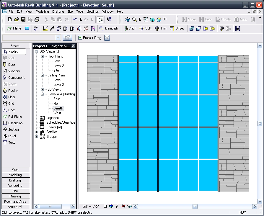
First: A Standard Elevation View:

Second: A 'Re-Oriented' 3D View with Shading W/ Edge graphics:

Third: That Re-Oriented View now rendered out to an image:

Finally: The new image inserted onto a sheet and composited (overlaid) with another Wire Frame view (actually a duplicate of the initial view used to render): Yes we can do that!!!
Have a great time and let me hear from you if you have any comments or questions!!!-J
Monday, November 06, 2006
Short Post, Huge Point!!! See the Comments too
CAD is BIM and vice versa.
More to follow...
OK I'm back...
Rise up.
CAD is dead: long live computer aided design
BIM is dead: long live building information management
-J
Monday, October 09, 2006
Wall Component Thickness Not Sickness

If you want to change these for all subsequent projects do this in your Project Template. At the command prompt...just kidding, I only want to make sure you're present...In a Plan View type V V (or VG but I find V V is faster, being just one letter repeated), there you will see the following...(follow the red arrows below)...

When we check the Cut Line Style box, then Edit we get to the dialog below (this is where we actually make our changes).

After we OK all the way out, your walls will reflect the changes you made, given that you made changes and are either in Medium or Fine Mode. (but wait, we're not home yet...) The example below illustrates the framing (structure) as being the most bold, since I always (or nearly) dimension to structure.

If you'd like these changes to become standard and or typical there is some thinking that we must do and some questions we must ask before we go on. Do these styles want to be different at different scales? Do they just want to be this way in Plan? etc., etc.
Either way when we make the appropriate choices for our needs we would create View Templates and apply them according to where they're necessary. I created these test images from a Plan Views 'View Template' but in real projects I normally have view templates for each different scale, in addition to Plan, RCP, ELEC. views at different scales, etc...There is a final (???) question to ask ourselves: Do these "Apply automatically to new views of same type"? (see image below). I find this is a 'sometimes' choice so be careful with that one.

Have a good time with this one, its fun and tasty.
Monday, October 02, 2006
Door Tags by Room Number: "Want 'em?" Got 'em"
In CADworld with it's non or semi intellegent lines, blocks, classes, property set definitions, etc. tagging items non-numerically was the norm for some of us and since we had to (some still have to) use (now in my opinion, waste) that time (sometimes days) creating Schedules in their CAD based projects. Again, those are really lost hours manually inputting text into schedules or creating data sets to the 'enth degree'; yet it's mandatory in the CAD packages I know of (sorry ADT, you too). Well...Not in Revit!!!
Firstly, in Revit I actually like to simply allow doors be numbered as they will be; thus not making extra "busy" work that doesn't necessarily impact the Architecture in a positive way (That is why I am here, right? the Architecture?! oh yeah I remember) -Although, I have a dirty little secret: I too renumbered my doors in the past, based on levels (100's, 200's etc.) but am doing well in my CAD Standards Therapy sessions and I'm coming up on my One Year of CADsobriety soon!!!
As i said previously: here's a solution for you to get that particular door-numbering-by-room standard put into Revit...where it will be coordinated; though you may have to help it along when adding new doors or removing others, etc. Also: Revit will try it's best to continue the numbering you last used so be aware of what you and Revit do...So finally:
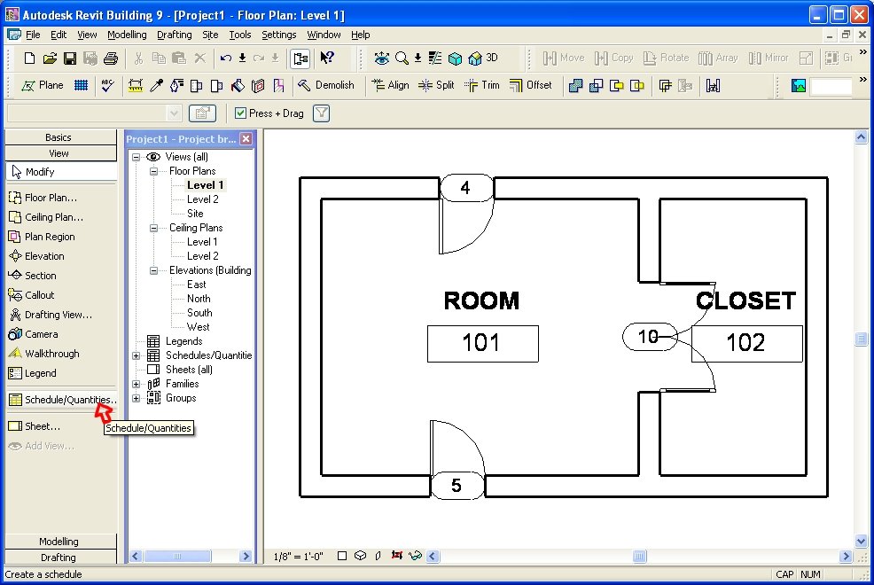
Our first image is a sample project with Doors tagged and Rooms placed:
Now we are ready to create a Door Schedule View: Our next image illustrates the beginnings of such. Add fields as you need from the "Doors" Fields...reorder them as needed...
What we do now is: Be Curious...select the "From Room: Number" field.
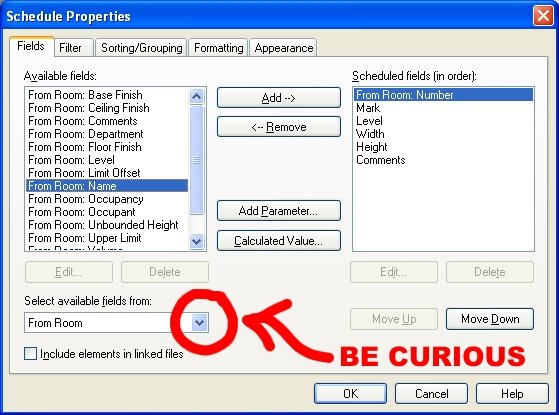
Then the "To Room: Number" field (Remember to re-order them as or if needed)
Now filter/sort/format and change the appearance settings if you need then complete the view...Next, renumber the "Mark" fields in the newly created schedule, according to your preferences...(Yes, this writes back to the actual door!!!)
But before we go there are a few "hidden" items...specifically "columns" that need hiding! Select the two 'Room ' columns, Right click and this is what you will see...yes choose to hide them!!!
After hiding these columns (yes, the schedule view can be right clicked at any time in the future, thus giving the choice to "show" them again, at any time...YEAH). Now we just need to place it all on a sheet and voila...Numbers by Rooms...Nearly automatic...And remember...we can do this once and save into our project templates and use it over and over!!!
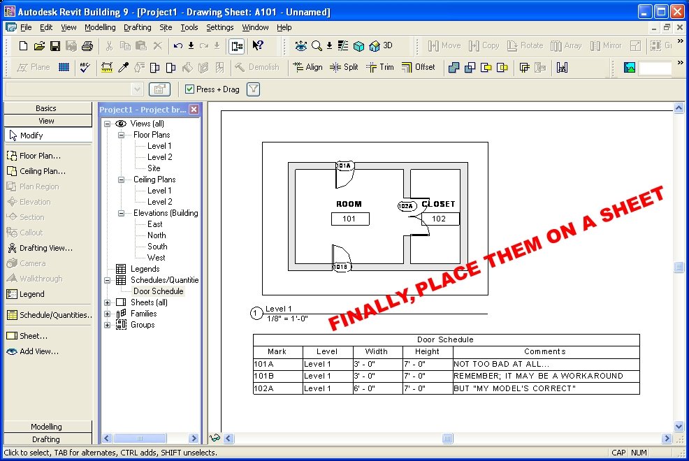
Take care!!! Thanks Daniel.-J
Monday, September 25, 2006
DGN Converter and More!!! Labs Rule!!!
I add that "left hand" comment because I found that Microstation is (was) a click-happy software that doesn't leverage (or even allow for the most part) the use of the left hand; if you are a right handed person, of course. (Hey Bentley, not only do many of us have 2 hands but we have this new thing: it's called a keyboard.) For all the lefties out here the converse would be the case, but I digress.
Take care,
Saturday, September 23, 2006
Dimensions: Prefix to Suffix Without a "Text Override"!!!
Well Hello Again,
As I ponder the difficulties that CAD World users enjoy and the growing advantages of BIM Town that others enjoy; I am again reminded of the ridiculous ability (my personal opinion, please don't be offended if you're "That CAD Person") to override a dimension with a 'fake' number. Now I know dimension overrides can be used to call something out for verification, etc. and I know too that we used them in the Prehistoric Hand Drafting times because we either didn't draw correctly, we didn't want to RE-draw something for just a few inches (or less), or we didn't want to take the liability on, etc.
(If you have arguments to why dimension text overrides should be used feel free to comment or email me but I bet I have an answer for each). BTW: A text overridden dimension is called a note, so why not use a note?
I will give you CAD Users one thing: Using only words in a text override can be useful and in my opinion can be benign, so you have my permission to use them: but you don't have my permission to fake in a number...That's why in all ACAD based products there is the command "DIMREASSOC". -Yeah, it re-associates all text overridden dimensions!!!
Down to the point: Revit has pure Suffix and Prefix properties that can be added to a real dimension. If you want the wall's dimension to report a 'pretty', round number then: "Move the Wall (.)" I stress the "period" in that sentence! No. I don't even feel we should clip the dimension tolerance. To me we should be in-putting our geometry, models, etc correctly(.) Anything less is asking for problems; not to mention incorrect and sloppy.
So: If you want a Prefix or Suffix in Revit then select the dimension in question.
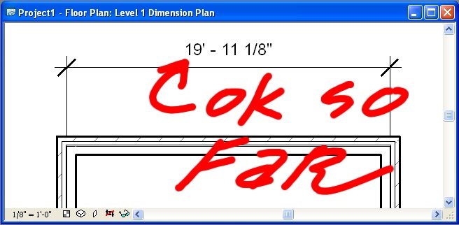
Then hit the 'Properties' button, on the 'Options Bar' and you'll see something like the following:
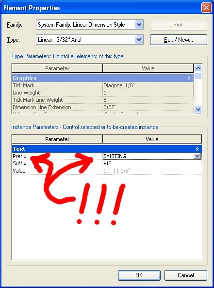
Enter the information you need and OK yourself all the way out. And yes, you will be OK!!!
Architectural Desktop & CAD World have these prefix and suffix "Options" and they are fantastic upgrades over the programming text we used to use; but one can still fake in the dimensions. Yeah, I know it may be your "CAD" standard to allow this but it is incorrect, limiting and in my opinion one of the worst things we can do: frankly it degrades Architects' standing in the industry with engineers, consultants, etc. as this is technically "incorrect information" being provided (except of course for the purely textual 'text overrides'. (I keep hearing from all sorts of people in the industry who laugh that Architects don't know what they are doing based on these bogus dimensions!!!).
-J
Saturday, September 16, 2006
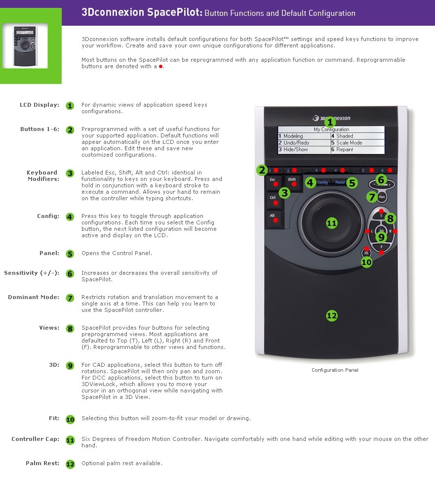
3D CONNEXION's SpacePilot: Now we're flying!!!

Well My hat is off to the folks at 3D Connexion for creating some of the coolest (not to mention useful) input augmentation digital manipulation tools, perhaps since the mouse (although I don't recommend the use of a mouse; I prefer a pen tablet for my main input device for "real" work. ...You know what 'they' say: OK, well maybe just I say it: "the pen 'tablet' is mightier than the mouse." -Plus with the tablet & SpacePilot I don't have to worry about getting carpal tunnel syndrome from dirty little rodents). Come-on, you know the mouse is always getting dirty...and they can f+*# up your carpals...
I have used my new SpacePilot for just 2 days but am already loving both the 3D & 2D computer life a little more because of it; plus I find myself reinvigorated; although that may be due to the fact that I live near the beach and USC won again...I'm not sure.
Well, back to the point of this post...
Pan, zoom, rotate, up/down, in out, etc. they are all dynamically modified, at any time (!!!), without having to enter into a command. (WOW). Additionally, all of their products have a multitude of programmable buttons; which is always needed (well, at least by me). It even saves custom setups that can be distinct for different softwares. Included in these are some presets for Maya, 3D MAX, VIZ, Inventor, Autocad, (thus Architectural Desktop and all the other Autocad based products) and hosts of other, sometimes surprising (in a good way) supported applications... Including PhotoShop, Acrobat, Outlook, etc., etc.
A collegue of mine uses the SpaceTraveler, which is really slick, being that it is so portable while being extremely functional. Being that he is the Mechanical Maniac, he finds it invaluable. (Shoot, should I have one of those too??? I believe that will have to happen for me). The Traveler was the first of these products that I both saw and got a chance to try: and I fell in love (with the whole line of the SpaceProducts immediately), after my first time (using one).
Though the pan and zoom aspects of the SpacePilot works in Revit, there is one limitation, at least for me personally, at this time and that is it isn't fully supported for use within Revit. (No dynamic rotate or any programmability yet). I believe this will soon be accomplished and it will become fully functional within Revit and when that day comes I will most assuredly update this Blog with that info!!!
So if you like to save time and would enjoy having greater and smoother control over the manipulating of your 3D & 2D Models, data, computer applications and environments like I do then definitely look into getting one of these great products...at least one!!!
-J
Friday, September 15, 2006
The Hollywood Guilds Demo

Hello Guild Members,
I am preparing a Demonstration for you showing Revit Building to illustrate how this technology can help streamline the Set Design Process, Pre-Visualization & Production of deliverables for you and your industry.
Please click either the "Revit in Hollywood" image above or the "Comments" link at the bottom of this post and add any requests, comments or questions you may have about this and I will either reply herein or include those ideas, examples in my demo. The demo will be scheduled to happen in the next few months.
After reviewing examples of typical, time sensitive projects required in your industry I am confident that you can realize, with the use of Revit, more design flexibility; more team input and continual production brainstorming and on the fly revisions, changes & options than can be achieved with either traditional hand drafting workflows or other not fully parametric, and/or line-based cad solutions.
By leveraging Revit's parametric change engine (how Revit works) one can have ultimate flexibility throughout the entire life of a project while maintaining a set of deliverables that not only can be built from but are actually (and always) coordinated. -the only way I can have an uncoordinated set of working drawings is by not printing!!! (-Well I could forget to give updated prints to the builders, but that is another matter entirely!!!)
Change something once and it changes everywhere. Immediately, everywhere.
Revit: REvise+InsTantly. -That is actually where the name came from, I am told.
I look forward to hearing from you,
-J
Tuesday, September 12, 2006
Publish 3D DWG's to Google Earth
Well, yes as a matter of fact I do!!!
It's finally here and easy enough to use. There is an early Beta version available from the Autodesk Labs site: Click Here!!!
There are also application/addons to Revit Building that can accomplish this as well (obviously in Revit) so I will post more info regarding that one in the next couple of days. I will also post some of my examples, but for now I thought you (all) should know!!!
-J
Thursday, August 24, 2006
Where are all those hand-drafting based firms?
Change or Die??? (Well he said parish, but you get the point) WOW, those are strong words...By The Way, Where are all those hand-drafting based firms?
We all know or have heard that, if one wants to generate something truly great they must take risks.
Moving to BIM may be a risk (though not in my opinion!!!) but any risk involved to it has so much potential and so many benefits
Courage is being able to act in the presence of fear.
Loathing is being in a state of reluctance.
...Where are you standing?
Friday, August 18, 2006
Make non-coplanar objects coplanar
Several years ago I finally had enough in regards to AutoCAD and the dreaded Z coordinates of objects always getting screwed up, usually after I xref'd in a consultants .dwg. Now, the issue wasn't that consultant's file, it was how AutoCAD works and me. If I snap to something 400 feet below, well it's my fault for not being aware. It was a tough thing to accept at first but once I realized that the error was in a belief of mine I was able to begin the path to enlightenment...at least in the realm of CADworld.After all it was only a belief of mine that the lines "were" or worse yet "should" be flat. (Those @*^#! 'unrealistic expectations' will get us every time!!!) ...I mean they "looked" flat and I was in my top view...
"uh oh, 'better check the side view...@*^#!" Sure enough, the lines were not coplanar. AutoCAD may be a lot of things but it usually doesn't lie!
One thing that I got from all of this (and I can't be happier about it) is the realization of this whole system of CADbelief that exists mostly just below our conciousness. It is so nice to be free, or at least getting there, as the struggle for my freedom from CADbelief goes on; just now with my eyes open (er).
Well to make a long story longer, I suggest that in addition to using the solution on this Blog that you read the white paper from Autodesk (Make non-coplanar objects coplanar) for this one, as they explain 2 ways of achieving the desired result. They also provide a great deal of support there, as they always do. (I believe (hahahaha) that their syntax is incorrect, as I used the ^C^C in the command, they only have one ^. I can attest that the button works as you can see the command in the CUI dialogue image above, if you click on it.
'That said here's my favorite way, their example #2...Make a custom button and paste in the following syntax to the macro area within that button in the CUI:
^C^C_move;_all;;0,0,0;0,0,1e99;_move;_p;;0,0,0;0,0,-1e99;
Then just click that new button whenever you have objects at incorrect Z coordinates; no need to select anything first, this works on everything (no it won't explode walls in ADT, etc) but it will bring xref's down to a Z of 0 so unload if need be.
The screen shot at the top of this post is the CUI editor and If you don't know your CUI then introduce yourself by typing CUI at the ACAD/ADT, etc. 2006 and 2007 Command Prompt!!!
If you've never been there then please click the link on the CUI dialogue box that says "Learn more about Customization" the CUI is a subject for another time (in this Blog).
-Enjoy!!!
Wednesday, August 16, 2006
Automatic Revisions, Tracking and Management? a CAD users dream; a Revit user's Reality!!!
First: Create a revision cloud in an appropriate view. (Menu Bar/Drafting Tab/Revision Cloud)
Second: Tag that cloud with a Catagory Tag. (if not present load it from the Annotations folder...yes, the family file is called "Revision Tag").

Third: go to SETTINGS/REVISIONS.
There you will create and manage revision info.
Finally place the view on a sheet (that has a Revision Schedule built-in to it, like the standard templates included with Revit!!! BOOM you will have the revision already filled out on the sheet before you can even say "wow").

Now, if you created your sheet templates by leveraging the families included in Revit you will already have a revision schedule built-in (barring its deletion). But if you imported and exploded a CAD template without then building a revision schedule in to the new Revit sheet family template you may want to go back and rebuild yourself new sheet family templates.
We need to carefully contemplate and make a distinction between what we believe to be benefits in reusing legacy CAD data and the realities of doing so. A shift in perceptions, habits and workflows is required if we are to create a successful BIM environment; the ways-of-the-CAD do not always translate, much like some of the hand-drafting practices that needed adjustment, integration or abandonment with the advent of the CAD workflow.
The transition to a BIM solution requires a great deal of suggestions and help. This should come from internal and external sources that can be relied upon to both brainstorm and also to help us with best practices and concepts for legacy content and so much more. A trusted, varied and experienced group of Revit support personnel can be your greatest asset. My intent is to be one of those voices.
When using Revit with an "onward and upwards" approach rather than a "copy from backwards" approach, in almost every case will enable success.
Tuesday, August 15, 2006
Beliefs, Myths and other beautiful lies
Before I can entertain discussions or comparisons between, say Architectural Desktop vs.
Before BIM (BIMtown) there was CAD (CADworld) where lines on a page were walls: Why? Well, we believed them to be.
In CADworld we overlay a highly formalized, sometimes enabling, yet restrictive belief system over our productions in order to have them function for us. Most of the time we don't even realize that we are attaching beliefs. As long as everyone involved in the project buys into this agreement reality then all will appear to be working. Dimension overrides and all!
If you fall into the category that feels that a line based CADworld reality is either equal to or superior to a model based BIMtown solution then I say “Welcome, sit back and get ready to be upset, shocked into life (or better yet; do you want to buy an old 386 pc or better yet a slide rule?)”.
We believe so fervently that we sometimes, if not always forget what is or was important to us. We get caught up in processes, formulae and habits, we then wear them like they're fluffy slippers. I hold to the ideal that Architecture and it's practice should be a creative act: even though that too is a hollow belief. What do I mean??? Well, any belief is only real as long as someone believes it.
Belief is not reality.
Reality is reality.
What is is.
Everything else, rationalizations, reasons, thoughts and beliefs are subjective and inevitably incorrect to someone.
When I am painting a canvas my creativity would get stale if I were to always use the same materials, brushes, etc. By forcing myself to explore new and possible solutions to an age old problem (painting a picture in this example) I find that it can be quite liberating, exciting and rewarding: yes, sometimes the result is unexpected (and this, I believe, is the best possible result) if one has talent and explores possibilities and takes risks that person or firm will see realized more outstanding results than were previously believed possible. This new excellence will be reflected in the work, no matter the discipline. When creating a building why not search out the best tools to enable innate talents to shine through, rather than holding on to outdated, limiting solutions? Is death that imminent? Are we too scared? I sure hope not!.
20 years or so ago most every building, even large building projects were drafted by hand. Where are those projects going to now? The hand drafters???
Fast forward to the beginning of the 21st century (now, then, whatever): Most building projects are being realized on and with a line-based CADWorld drafting solution...much better than drawing by hand, (although not as fun or dirty) but not as efficient as Object-based midBIM (Architectural Desktop, etc.) or BIMtown (Revit Building, etc.).
Back in the 1980's if you were around; did everyone immediately embrace CADworld? Not likely. But those who did take that first leap (first); back when hair was big and punk rock went into a temporary hiding; found that they were able to do things in their A/E practices that reinvigorated them, their ideas, their coworkers and their sex lives...(ok maybe that's a stretch but I sure felt like I was on the cutting edge and I strived for more than I had before).
Now we are again back in those proverbial times, NO not the 80's! Now we have more piercings, tatt's and fake body parts, but we find ourselves at a crossroads between that line-based CADworld; a falsely comfortable past way of being; and an unfamiliar BIMtown future.
Who will lead, who will follow and who will find themselves outside looking out because they wanted to hold on to a CAD standard, a CAD software or any number of other means to an end?
The end I strive toward is producing and enabling others to produce and realize their creative ends by leveraging the best possible solution and in CADworld it is appearing more and more like midBIM may be an ok, even exceptional interim step but BIMworld may very well be (is) the way to go.
What do you believe?
Check back in 10 to 20 years to see if I am correct.
-J