Looks like I missed the new Revit 2008 Build a week or two ago (20070810 1700), how about you? Well now we can all have it!!!
What it does:
RAC2008 SP2 List.pdf
Where to get it:
Right About Here.
Now make some more families!!!
Thursday, August 23, 2007


Wednesday, August 22, 2007
Do Not Use Internet Explorer. But do use Revit like Revit!!!
In addition to potentially allowing every hacker into our computers, internet explorer (IE) may not show you text properly in some of my posts.
Today a colleague was reviewing how to apply the line based family concept with me and I noticed the text parts of the trellis steps, in the last post had all sorts of formatting oddities (yes he was using IE...though I didn't get the version).
Needless to say that leaves the content (next to) unusable for him and I guess others (sorry for that but you have to call Bill Gates out on that one). I will try to format my copy/paste differently into the future, but if you use IE don't blame me if you can't read my text or get a back door worm from Paris or Britney...
To quote cOmrade, the hacker who got into The Pentagon and NASA systems, from an August 21, 2007 issue of PC Magazine ..."Oh--and don't use internet explorer."
Shit, I heard that loud and clear years ago, that's why I never checked to see if this Blog looks OK in IE...Firefox blows it away!!! One word: DownThemAll!!!
I know cOmrade isn't the first and won't be the last to illustrate the shortcomings of IE, but I think you get my point...
Today a colleague was reviewing how to apply the line based family concept with me and I noticed the text parts of the trellis steps, in the last post had all sorts of formatting oddities (yes he was using IE...though I didn't get the version).
Needless to say that leaves the content (next to) unusable for him and I guess others (sorry for that but you have to call Bill Gates out on that one). I will try to format my copy/paste differently into the future, but if you use IE don't blame me if you can't read my text or get a back door worm from Paris or Britney...
To quote cOmrade, the hacker who got into The Pentagon and NASA systems, from an August 21, 2007 issue of PC Magazine ..."Oh--and don't use internet explorer."
Shit, I heard that loud and clear years ago, that's why I never checked to see if this Blog looks OK in IE...Firefox blows it away!!! One word: DownThemAll!!!
I know cOmrade isn't the first and won't be the last to illustrate the shortcomings of IE, but I think you get my point...
Thursday, August 09, 2007
Line Based Families 1: Kitchen Cabinets...OK, OK And a Trellis...
Firstly: these concepts and (maybe) all family methods can be transposed to many, many other families; at times exactly, at times similarly, at times just in spirit.
Consider, Plan, Think, Re-Consider, Re-Think, then Create.
Consider (what you want), Plan (the parametric needs), Think (about what is needed NOW... Remember you can always make the family progressively more complex), Re-Consider (how complex it needs to be), Re-Think (the final output needs...don't put in any more than you need but no less either), then Create (the best family you can). Also mix-in a conversation with others...this always helps prove or disprove perceived concepts and usually saves overall project time.
The Cabinet family we are about to create (well similar parameters to this, at least) can be used for many other families, one of which I will include a step-by-step of (in text format). It will be the main portions of a trellis.
More about the Trellis following the Cabinet below, so on with the Cabinet sheooow...(Yeah, I was watching a repeat of Elvis on the Ed Sullivan Show...sorry for that rhyme, etc.)
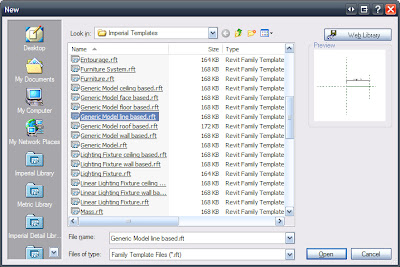
1) Create a new 'Generic Model Line Based' family.
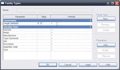
 2) Change the "Length" parameter to 8'-0" via the "Family Types..." button.
 Just like this...
 Good so far...
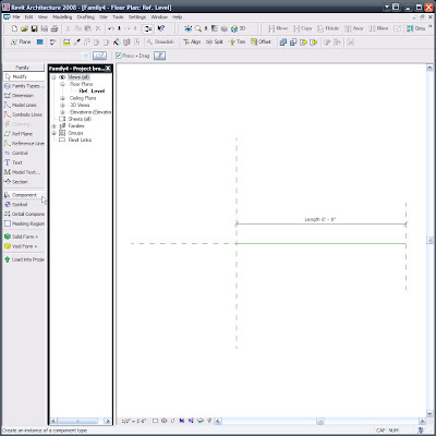
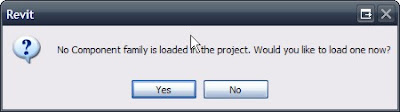
3) Load a Cabinet. (If you don't already know, this is what is called nesting a family. I like to call them bird families...) -yes that's a (bad) joke!
 I am using the Double Door & 2 Drawer, as you can see.
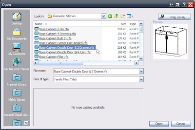
Note how this cabinet comes in at it's default size...we'll be synchronizing and locking that to a parameter later but since we haven't created the parameter yet we'll do some other necessary work first...
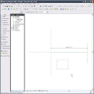
Such as Locking the Cabinet to the Ref Planes. (Note: To get this line based family to work this time I did have to re-do this locking after I constrained the objects to the upcoming parameters, (last time I showed a colleague this it worked fine, without re-locking...It's all about process) so be ready for the family to potentially fight you as you go...Flex every step of the way so it's not too painful.)
Align/Lock to the start:
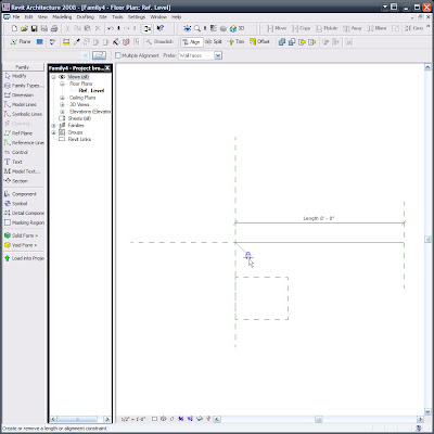
Align/Lock to the insertion point (Yes, the intersection of these Ref Planes is the insertion point, so if you need an offset insertion be aware of that):
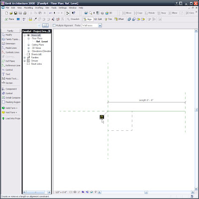
Where are now, #4)? I think so...No matter, the next one may seem odd no matter the number.
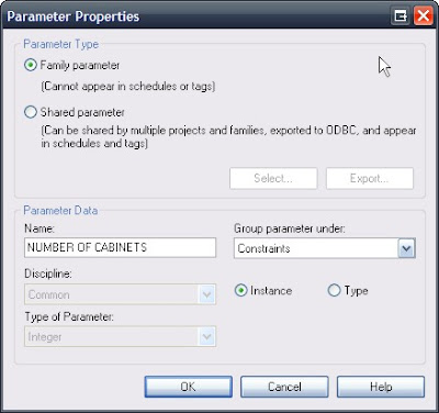
Array the cabinet 3 times; constrained, grouped & associated. Then select one of the array group members and select the Array Control Line, (the odd part is the Array Control Line disappears when you're able to select it) add the parameter "NUMBER OF CABINETS" (similar to the one that follows the next image) and it will then be associated to the array.
Below is an image of the Control Line selected...The oddity is that the Control Line seems to disappear or at least go invisible when hovering over it, so if you want to select it (and we do) and that control line disappears then click there, you are sure to select it since it looks like you can't. Yes that IS what I said. Perhaps at AU I can get an answer from a developer as to why this is the case....
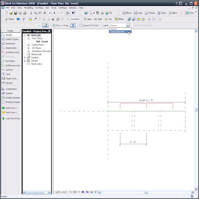
Here's the "NUMBER OF CABINETS parameter's" parameters: (Nice use of the language/lingo -I think)...
5) -Or is it 11?...Anyways, again Via clicking the "Family Types..." button we can and must set up the following additional, necessary Parameters:
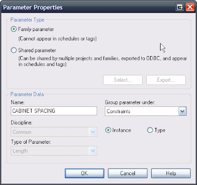
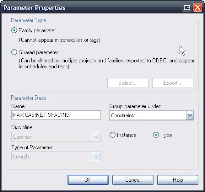
This last parameter I attributed to the dimension below:
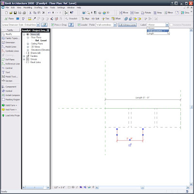
Now, you should know that when I entered the formulas, per the following image (which you can and really must consider as being the next step!!!) the dimension (shown above) needed to be deleted. I let that happen and didn't question it later on since the family works without it (as long as you don't set the overall length below 6'-0"... yes we could place more constraints via a conditional statement to allow for that but for this particular family I didn't find it necessary to have a multiple, double cabinet be so small...I say let it break in that case, it's just too illogical)
So now make the parameters be the following formulas and values, making sure to hit APPLY after inputting each formula. (Remember formulas ARE case sensitive!!!)
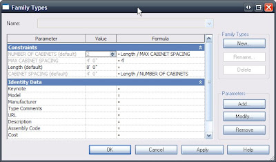
This time while I was creating this line based cabinet family (and after letting the dimension be deleted during the error/warning stage) the middle cabinet disappears...There is actually a good reason for that and I eluded to it earlier, way back in step #3... Even if you don't care to go back and look here is the 'fix'.
Step Whatever): Edit one of the Array Groups and select the cabinet and click the Properties button:
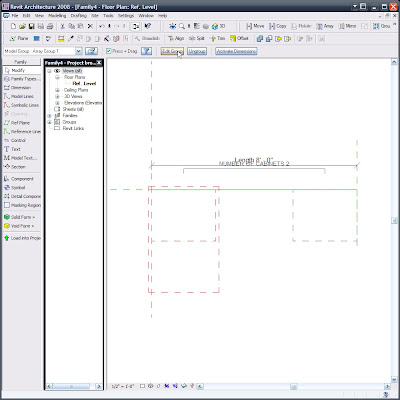
When you get down into it's Type Parameters look for the Width parameter and click the tiny little = (equal) button...(Actually I think Autodesk tried to hide that = button from us :-))
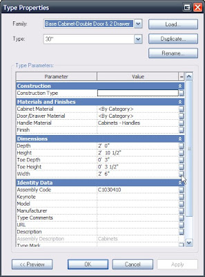
Now set that equivalence of the Length parameter to CABINET SPACING.
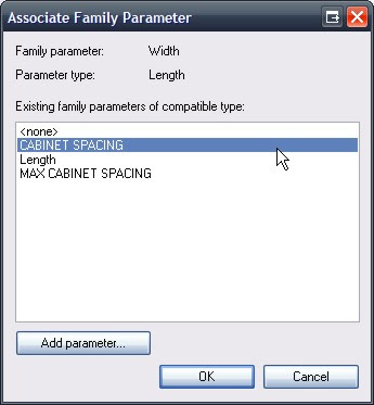
Now everything seems to work brilliantly!!!
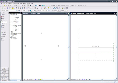
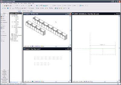
So we can load it into a project and input them via the Component command.
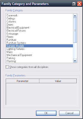
One final note: We may (actually we do!!!) want to go to SETTINGS/FAMILY CATEGORY AND PARAMETERS...:
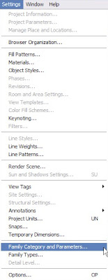 and set (unless we previously set this) Line Based Families' "Family Category to be Casework, like below... But if not we can do it anytime and then reload!!!
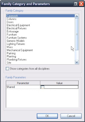 This goes for exposing materials, etc., etc., ...
NOW FOR THAT TRELLIS:
I am only including the text of it since the step-by-step takes about an hour to demonstrate live (with talking :-)) and with screen captures added would take me a lot longer and enough is enough for tonight!!! Also note that the trellis recipe may require some interpretation, since it is purely a copy/paste of my personal notes, for demonstration purposes (By the way, this Demo kicked some ass and opened some eyes at the LA RUG meeting in July where I presented it for the more than 100 Rev-Heads in attendance). The reason that I say all this is that the directions are (mostly) in exact order, yet may possibly be in need of connecting some dots... In any case I hope those directions help and well, I am confident that they will, but if you need help just drop me a comment and I'll help you out further. See you soon!!! -J
Consider, Plan, Think, Re-Consider, Re-Think, then Create.
Consider (what you want), Plan (the parametric needs), Think (about what is needed NOW... Remember you can always make the family progressively more complex), Re-Consider (how complex it needs to be), Re-Think (the final output needs...don't put in any more than you need but no less either), then Create (the best family you can). Also mix-in a conversation with others...this always helps prove or disprove perceived concepts and usually saves overall project time.
The Cabinet family we are about to create (well similar parameters to this, at least) can be used for many other families, one of which I will include a step-by-step of (in text format). It will be the main portions of a trellis.
More about the Trellis following the Cabinet below, so on with the Cabinet sheooow...(Yeah, I was watching a repeat of Elvis on the Ed Sullivan Show...sorry for that rhyme, etc.)
1) Create a new 'Generic Model Line Based' family.
 2) Change the "Length" parameter to 8'-0" via the "Family Types..." button.
 Just like this...
 Good so far...
3) Load a Cabinet. (If you don't already know, this is what is called nesting a family. I like to call them bird families...) -yes that's a (bad) joke!
 I am using the Double Door & 2 Drawer, as you can see.
Note how this cabinet comes in at it's default size...we'll be synchronizing and locking that to a parameter later but since we haven't created the parameter yet we'll do some other necessary work first...

Such as Locking the Cabinet to the Ref Planes. (Note: To get this line based family to work this time I did have to re-do this locking after I constrained the objects to the upcoming parameters, (last time I showed a colleague this it worked fine, without re-locking...It's all about process) so be ready for the family to potentially fight you as you go...Flex every step of the way so it's not too painful.)
Align/Lock to the start:

Align/Lock to the insertion point (Yes, the intersection of these Ref Planes is the insertion point, so if you need an offset insertion be aware of that):

Where are now, #4)? I think so...No matter, the next one may seem odd no matter the number.
Array the cabinet 3 times; constrained, grouped & associated. Then select one of the array group members and select the Array Control Line, (the odd part is the Array Control Line disappears when you're able to select it) add the parameter "NUMBER OF CABINETS" (similar to the one that follows the next image) and it will then be associated to the array.
Below is an image of the Control Line selected...The oddity is that the Control Line seems to disappear or at least go invisible when hovering over it, so if you want to select it (and we do) and that control line disappears then click there, you are sure to select it since it looks like you can't. Yes that IS what I said. Perhaps at AU I can get an answer from a developer as to why this is the case....

Here's the "NUMBER OF CABINETS parameter's" parameters: (Nice use of the language/lingo -I think)...

5) -Or is it 11?...Anyways, again Via clicking the "Family Types..." button we can and must set up the following additional, necessary Parameters:


This last parameter I attributed to the dimension below:

Now, you should know that when I entered the formulas, per the following image (which you can and really must consider as being the next step!!!) the dimension (shown above) needed to be deleted. I let that happen and didn't question it later on since the family works without it (as long as you don't set the overall length below 6'-0"... yes we could place more constraints via a conditional statement to allow for that but for this particular family I didn't find it necessary to have a multiple, double cabinet be so small...I say let it break in that case, it's just too illogical)
So now make the parameters be the following formulas and values, making sure to hit APPLY after inputting each formula. (Remember formulas ARE case sensitive!!!)

This time while I was creating this line based cabinet family (and after letting the dimension be deleted during the error/warning stage) the middle cabinet disappears...There is actually a good reason for that and I eluded to it earlier, way back in step #3... Even if you don't care to go back and look here is the 'fix'.
Step Whatever): Edit one of the Array Groups and select the cabinet and click the Properties button:

When you get down into it's Type Parameters look for the Width parameter and click the tiny little = (equal) button...(Actually I think Autodesk tried to hide that = button from us :-))

Now set that equivalence of the Length parameter to CABINET SPACING.

Now everything seems to work brilliantly!!!

So we can load it into a project and input them via the Component command.

One final note: We may (actually we do!!!) want to go to SETTINGS/FAMILY CATEGORY AND PARAMETERS...:
 and set (unless we previously set this) Line Based Families' "Family Category to be Casework, like below... But if not we can do it anytime and then reload!!!
 This goes for exposing materials, etc., etc., ...
NOW FOR THAT TRELLIS:
I am only including the text of it since the step-by-step takes about an hour to demonstrate live (with talking :-)) and with screen captures added would take me a lot longer and enough is enough for tonight!!! Also note that the trellis recipe may require some interpretation, since it is purely a copy/paste of my personal notes, for demonstration purposes (By the way, this Demo kicked some ass and opened some eyes at the LA RUG meeting in July where I presented it for the more than 100 Rev-Heads in attendance). The reason that I say all this is that the directions are (mostly) in exact order, yet may possibly be in need of connecting some dots... In any case I hope those directions help and well, I am confident that they will, but if you need help just drop me a comment and I'll help you out further. See you soon!!! -J
1) New Family “Generic Model” (Square Column)
a. B Wd (B = Beam, C = Column, etc.)
b. B Ht
c. B Lng
d. C Wd
e. C Dp
f. C Top
3) Create Square Colum
a. Use the 3 shared Parameters: C Wd, C Dp, C Top
4) Create Round Column (Save As ???)
a. Use the 3 shared Parameters and Add:
b. C Rad (Make this equal the following formula)
i. = C Wd / 2
5) Make
a. B Wd =
b. B Ht = C Top+1.5
c. B Lng =
d. C Wd =
e. C Dp =
f. C Top =
6) New Family “Generic Model”
7) Create Beam
a. Use the 3 shared Parameters: B Wd, B Ht, B Lng
8) New Family “Generic Line Based”
a. Make Length 8’-0”
9) Insert Beam Perpendicularly to length line, Place it and Lock.
10) Copy it to the opposite end & Lock.
11) Add & Place Columns
12) Create a ‘Family Types’ Instance Parameter: Column Type and choose Generic Models. (or change column & beam families to their actual category and use those here)
a. Select all columns and set them to have the parameter Column Type.
13) Array 1st beam 2’-0”: Group & Associate, Move to 2nd, Constrain.
a. Select the Arrayed Beam and select the Array Control Line and add a Parameter: “Number of Beams”, Constraints, Instance and OK.
14) Dimension the 1st & 2nd Beams
a. Make it the Parameter “Beam Spacing”, Constraints, Instance and OK.
15) GoTo Family Types and add the following Parameter:
a. “Maximum Beam Spacing” , Constraints, Common, Length, Type OK in this dialog, then APPLY at the next; (Not OK…we want to stay in this dialog for a minute).
16) Make the Parameters the following Formulas:
a. Maximum Beam Spacing = 4’-0”
b. Number of Beams = Length / Maximum Beam Spacing
c. Beam Spacing = Length / Number of Beams
Friday, August 03, 2007
The (Revit) thoughts that come with a fever. AKA: Trumping the 'In Place Revit Family: The Floor' post ...Even if I suggested it.
So Hello there once again. I posted in last week's (In Place Revit Family: The Floor) that we can create a metal deck (looking) floor with an in place family. Well, that's true enough but it (the in-place family aspect) kept bothering me (not really) since for one, the in place floor won't be cut by an opening such as a shaft, it won't have multiple materials, etc. Actually it seems that this stuff really does bother me, because yesterday while sleeping off the flu I woke up at about 1 am and realized something that seems blatantly obvious now...Create a normal floor and use an in place generic 'void' family and cut that from the floor!!! Then the floor will be a real floor having all the flooriness we have come to love from Revit floors, including the ability to be cut, have materials etc. MULTIPLE YAAY!!!
1. Create a floor (NOT SHOWN)... I think we can all do that, right?
2. Next, From an elevation view (perpendicular to the desired deck direction) GoTo MODELING/CREATE and choose Generic Model...(this will make the in place kind, remember?)
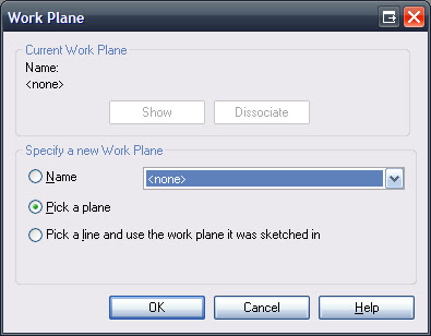
 3. On the Modeling Tools choose "Void Form" and if you need the metal pan similar to the one I used choose the Void Extrusion... In order to draw the lines delineating the decks 'corrugation' I picked the floor plane that is staring at me (from the elevation view). 'Tab' may need to be employed to get the correct face... don't choose the top of the floor!!!
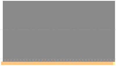
 4. Next, using those lines (obviously) draw the shape to be voided out of the floor.
 5. Just before finishing the family make sure the extrusion is long enough to cut the entire length of the floor in question, then using the "Cut Geometry" tool...
 Cut the void from the floor. Finish the family and now a better "voilà"
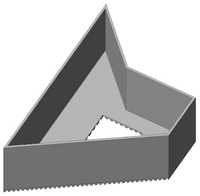 Oh and as you can see from above a normal shaft opening cuts our floor...A truly elegant solution. Thanks Revit!!!
1. Create a floor (NOT SHOWN)... I think we can all do that, right?
2. Next, From an elevation view (perpendicular to the desired deck direction) GoTo MODELING/CREATE and choose Generic Model...(this will make the in place kind, remember?)
 3. On the Modeling Tools choose "Void Form" and if you need the metal pan similar to the one I used choose the Void Extrusion... In order to draw the lines delineating the decks 'corrugation' I picked the floor plane that is staring at me (from the elevation view). 'Tab' may need to be employed to get the correct face... don't choose the top of the floor!!!
 4. Next, using those lines (obviously) draw the shape to be voided out of the floor.
 5. Just before finishing the family make sure the extrusion is long enough to cut the entire length of the floor in question, then using the "Cut Geometry" tool...
 Cut the void from the floor. Finish the family and now a better "voilà"
 Oh and as you can see from above a normal shaft opening cuts our floor...A truly elegant solution. Thanks Revit!!!
Thursday, July 26, 2007
Name, Rename & More from a Revit Schedule
First, I want to get something out of the way: distinguishing the differences between "simple" and "easy".
Using Revit is easy (especially when we 'Use Revit like Revit'
Using Revit is not simple.
Anyone who says Revit is simple is either full of shit or has no grasp of the words meaning. (And: I apologize if I ever said or intimated that Revit is simple...If I did say that it's simple then I'd like to clarify and say it's easy...mostly, not simple). Sorry folks, there is no "push button Architecture" Nothing comes from no work!!!
WTF do I mean? Well let's see what Merriam Webster says about:
Easy:
1 a: causing or involving little difficulty or discomfort (Like when Revit and the user are both at their best)
3 a: marked by peace and comfort (Like when Revit and the user are both at their best)
Simple:
4 a: lacking in knowledge or expertise ('Can't get much done in Architecture, etc. that way)
5 b: free of secondary complications (Doesn't sound like Revit...or Life...)
NOW that that's over with here is an easy way to Name, Rename (or More) views or sheets, etc.
Use a Revit Schedule! Actually we use 'View Lists' and 'Drawing Lists' (we must use the VIEW/NEW...per the image below, because these are some of the few items NOT on a Tool Bar)
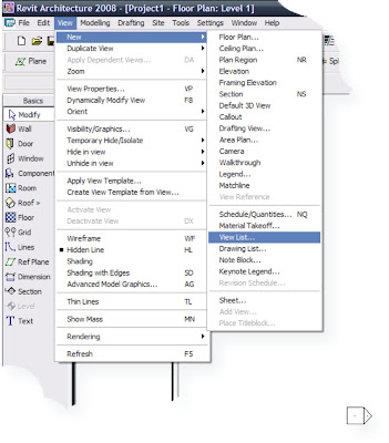 Uhhh by the way, Autodesk, do you see the symbol that you call an Elevation marker? It's simple (and as long as you keep it around so are you...Please change it!!!) -Is it insane of me to speak toward a corporation as if it's a person??? Better yet a person who is listening to me!!!
Back to business...
The issue herein is that I needed to change a whole bunch of views' names.
If I am editing objects that can be seen in the model then I tile the appropriate view(s) along side the schedules and work from the schedule to then make wholesale, or multiple changes...thus the easy...not to mention faster, better & more Revit-like way). YEEEHAAA, using Revit like Revit.
The Image Below:
1: What needs to be Renamed.
2: Why we need to Rename it.
3: Painful to Rename more than a few views from the Project Browser (PB).
Plus there are more clicks to get to information to/from the PB than can be at our fingertips from a schedule...On Demand Information (ODI for the TLA folks) I like it!!!
...the info, not the TLA's...
4: The solution of choice. If you need to Rename or add info then type the info once, CTRL+C then just click and paste (CTRL+V) to rename... But what I needed, as illustrated below was easier...I just had to click/select (one step if you're a bit careful) and delete the now useless info...
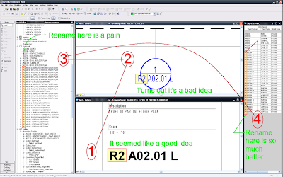 The moral of the story is: If it can be scheduled then it can be changed from a schedule; Easily.
Makes sense when we see it like that, doesn't it??? Revit Like Revit.
-J
Using Revit is easy (especially when we 'Use Revit like Revit'
Using Revit is not simple.
Anyone who says Revit is simple is either full of shit or has no grasp of the words meaning. (And: I apologize if I ever said or intimated that Revit is simple...If I did say that it's simple then I'd like to clarify and say it's easy...mostly, not simple). Sorry folks, there is no "push button Architecture" Nothing comes from no work!!!
WTF do I mean? Well let's see what Merriam Webster says about:
Easy:
1 a: causing or involving little difficulty or discomfort (Like when Revit and the user are both at their best)
3 a: marked by peace and comfort (Like when Revit and the user are both at their best)
Simple:
4 a: lacking in knowledge or expertise ('Can't get much done in Architecture, etc. that way)
5 b: free of secondary complications (Doesn't sound like Revit...or Life...)
NOW that that's over with here is an easy way to Name, Rename (or More) views or sheets, etc.
Use a Revit Schedule! Actually we use 'View Lists' and 'Drawing Lists' (we must use the VIEW/NEW...per the image below, because these are some of the few items NOT on a Tool Bar)
 Uhhh by the way, Autodesk, do you see the symbol that you call an Elevation marker? It's simple (and as long as you keep it around so are you...Please change it!!!) -Is it insane of me to speak toward a corporation as if it's a person??? Better yet a person who is listening to me!!!
Back to business...
The issue herein is that I needed to change a whole bunch of views' names.
If I am editing objects that can be seen in the model then I tile the appropriate view(s) along side the schedules and work from the schedule to then make wholesale, or multiple changes...thus the easy...not to mention faster, better & more Revit-like way). YEEEHAAA, using Revit like Revit.
The Image Below:
1: What needs to be Renamed.
2: Why we need to Rename it.
3: Painful to Rename more than a few views from the Project Browser (PB).
Plus there are more clicks to get to information to/from the PB than can be at our fingertips from a schedule...On Demand Information (ODI for the TLA folks) I like it!!!
...the info, not the TLA's...
4: The solution of choice. If you need to Rename or add info then type the info once, CTRL+C then just click and paste (CTRL+V) to rename... But what I needed, as illustrated below was easier...I just had to click/select (one step if you're a bit careful) and delete the now useless info...
 The moral of the story is: If it can be scheduled then it can be changed from a schedule; Easily.
Makes sense when we see it like that, doesn't it??? Revit Like Revit.
-J
Monday, July 23, 2007
In Place Revit Family: The Floor
Well, I have been asked to show a colleague how to create a metal deck floor. YAAY!!!
First I asked the user (as you should ask yourself) if they (or you) actually needed it in the model or will illustrating the corrugation in a detail suffice: refraining from modeling this floor would keep the file smaller, more flexible and a bit more streamlined to edit, etc.
Well, the answer came back that they want it in the model, so here we go...
First I created a bogus project to illustrate the following procedures: I already have levels and grids so defining Work Planes will be simple: I will use Grid J (Hey, what a nice coincidence).
The 'Project' waiting for the 'floor'.
 On the Modeling Tools choose 'Create'. This will begin the create an "In-Place-Family" portion of our show.
 Choose "Floors" (somewhat obvious since we want to create a floor). This is going to make our In-Place-Family a Floor Family. Always remember that when creating any kind of family (In-Place or Component) you must choose a category; if one does not correspond to the object you are creating then use "Generic Models".
 Name the family...Be specific so you can tell it apart from others you create!!! BTW: "Floor 1" is probably something I'd NEVER use on an actual project...you know, do as I say, not as I do...(a day without hypocrisy is a day of hypocrisy)...???...
 Now we're ready to model. For this we'll use a "Solid Extrusion" for the body of the floor.
 Set the Work Plane (as I said I am using Grid J...Nice name...)
 When I choose a grid, in order to draw perpendicularly to the plan view we are in (if we are in one) Revit will ask us to open a corresponding Elevation or Section View, so know your views!!!
Also remember to set the depth of the extrusion to a depth that will make it easy to see, you can stretch it's depth into final placement, easily enough, later on. I find it best, in many cases to stretch extrusions later (rather than calculating them up front) as it also makes locking it, much simpler.
7) Now that we're in 'sketch mode' draw the actual profile needed. Lines? How quaint...
 When you're done drawing the extrusion's profile then "Finish Sketch" but don't Finish Family, yet. We still need to create a few voids (or would you prefer to use shaft openings? Well good luck getting shaft openings to cut the In-Place Floor: let me know how that works for you...if you try it).
BTW: notice I am stretching the extrusion length in the image below, right? You would lock it if needed.
 Now create any Void Extrusions necessary. Note: I made them -2'-0" since they begin at the level and need to cut downward. Also the wedge shape needed to be a separate void and needed to leverage the Cut Geometry tool. Your results will vary, this is one of the times CTRL+Z becomes handy, quite possibly...
 When you finish the voids then finish the family...and...voilà:
 A Metal Deck Floor...Well OK maybe we didn't make the materials 'metal' (yet) but you get the point...Right?
Take Care,
-J
First I asked the user (as you should ask yourself) if they (or you) actually needed it in the model or will illustrating the corrugation in a detail suffice: refraining from modeling this floor would keep the file smaller, more flexible and a bit more streamlined to edit, etc.
Well, the answer came back that they want it in the model, so here we go...
First I created a bogus project to illustrate the following procedures: I already have levels and grids so defining Work Planes will be simple: I will use Grid J (Hey, what a nice coincidence).
The 'Project' waiting for the 'floor'.
 On the Modeling Tools choose 'Create'. This will begin the create an "In-Place-Family" portion of our show.
 Choose "Floors" (somewhat obvious since we want to create a floor). This is going to make our In-Place-Family a Floor Family. Always remember that when creating any kind of family (In-Place or Component) you must choose a category; if one does not correspond to the object you are creating then use "Generic Models".
 Name the family...Be specific so you can tell it apart from others you create!!! BTW: "Floor 1" is probably something I'd NEVER use on an actual project...you know, do as I say, not as I do...(a day without hypocrisy is a day of hypocrisy)...???...
 Now we're ready to model. For this we'll use a "Solid Extrusion" for the body of the floor.
 Set the Work Plane (as I said I am using Grid J...Nice name...)
 When I choose a grid, in order to draw perpendicularly to the plan view we are in (if we are in one) Revit will ask us to open a corresponding Elevation or Section View, so know your views!!!
Also remember to set the depth of the extrusion to a depth that will make it easy to see, you can stretch it's depth into final placement, easily enough, later on. I find it best, in many cases to stretch extrusions later (rather than calculating them up front) as it also makes locking it, much simpler.
7) Now that we're in 'sketch mode' draw the actual profile needed. Lines? How quaint...
 When you're done drawing the extrusion's profile then "Finish Sketch" but don't Finish Family, yet. We still need to create a few voids (or would you prefer to use shaft openings? Well good luck getting shaft openings to cut the In-Place Floor: let me know how that works for you...if you try it).
BTW: notice I am stretching the extrusion length in the image below, right? You would lock it if needed.
 Now create any Void Extrusions necessary. Note: I made them -2'-0" since they begin at the level and need to cut downward. Also the wedge shape needed to be a separate void and needed to leverage the Cut Geometry tool. Your results will vary, this is one of the times CTRL+Z becomes handy, quite possibly...
 When you finish the voids then finish the family...and...voilà:
 A Metal Deck Floor...Well OK maybe we didn't make the materials 'metal' (yet) but you get the point...Right?
Take Care,
-J
Tuesday, July 17, 2007
Revit Error Reporting: Again, Just Do It!!!
Well it happens to everyone sometimes: An Unrecoverable Error Has Occured... UGHHH. If (when) this does happen please send those error reports!!! it's not just to give you a feeling that ADSK is working for you; they actually want to fix the issue and when they do it helps all of us!!!
On their site, there is this page relating to the explanations and this link is a cute (not really) picture illustrating what happens to these messages.
On with the show: "After the Crash" and yes, I saved a recovery file...
Use the following dialog to help ADSK help us!!! See image 3 as well but please use the "Step by Step Description" area to give as much info to them as possible (I know you're busy but if you want ADSK to get rid of the issue you experience you have to let them know what was happening. Take pains to communicate... or at least say something...

Image 1 below is the "details" page for your edification & paranoia abatement.

Image 2 below is the "What Happens" web page...

Image 3 below is their helpful hints as to what kind of info helps them help us:
 Finally: Image 4 below is (I hope) obvious enough...

In an odd way I have always felt a little better after receiving the following 'thank you' from ADSK... It is almost (ALMOST) like I never had a problem whatsoever...
AAAHHHHHH, now isn't that better???
On their site, there is this page relating to the explanations and this link is a cute (not really) picture illustrating what happens to these messages.
On with the show: "After the Crash" and yes, I saved a recovery file...
Use the following dialog to help ADSK help us!!! See image 3 as well but please use the "Step by Step Description" area to give as much info to them as possible (I know you're busy but if you want ADSK to get rid of the issue you experience you have to let them know what was happening. Take pains to communicate... or at least say something...

Image 1 below is the "details" page for your edification & paranoia abatement.

Image 2 below is the "What Happens" web page...

Image 3 below is their helpful hints as to what kind of info helps them help us:
 Finally: Image 4 below is (I hope) obvious enough...
In an odd way I have always felt a little better after receiving the following 'thank you' from ADSK... It is almost (ALMOST) like I never had a problem whatsoever...

AAAHHHHHH, now isn't that better???
Wednesday, July 11, 2007
The Greening of Architectural Production: Using Revit like Revit
Using Revit like Revit? WTF? What a concept.
It's actually a bigger issue than many imagine. Additionally this concept seems not to be so obvious to everyone using Revit (maybe misusing?), or possibly worse yet, it may not be obvious to those implementing or considering implementing Revit.
I try to follow these guidelines when using Revit:
Use Revit Like Revit.
Do what I Know how to do.
Learn what I don't know that I don't know.
Incorporate.
Repeat.
Revit As Revit
There are actually 2 main concepts here:
1) "Using Revit like Revit". This one's in our personal & Professional scope.
Modeling what's appropriate, When appropriate, not trying to force CAD strategies on a BIM solution. Just because it seems to be a comfortable or viable position to use CAD strategies often it's not. Even if Autodesk says (or intimates) it works really well (such as using...even exploding (YIKES) AutoCAD files in Revit)...What are your AutoCAD angular tolerances set to??? -We'll talk about this later...
The following is a serious, friendly warning: IF YOU EXPLODE .DWG FILES DIRECTLY INTO A WORKING PROJECT THEN I HOPE YOU WANT TO LIVE WITH A TON OF FUCKED UP GEOMETRY, NAMES AND MORE THAN LIKELY NUMEROUS, POSSIBLY HUNDREDS OF ERRORS & WARNINGS.
2) "Revit working like Revit".
This one's in Autodesk's Professional scope.
Although it sometimes requires our guiding, nudging, pleading, ____ing of Autodesk to more fully develop Revit so that it works like Revit; -Or at least so it works like their sales force & Marketing Materials & fAQ's say it does.
In regards to #1: It has been my experience that trying to use Revit in ways similar to whateverCAD, or using Revit with or based on whateverCAD processes usually leads to a great deal of pain that in most cases can be avoided by just using Revit like Revit. Even if you have to learn how to use Revit more fully and even if there are new pains using Revit...The fascist UI for instance.
Want an example? Well, it seems to be logical for some users to think that linking (or worse Importing) all of their AutoCAD base files, or details (etc.) into their Revit Project(s) is a useful approach... especially since this work flow is actually spoken about as being viable by agents of or around Autodesk. I say Yikes!!! (Yes we may in the short-term need to leverage SOME cad files) but it should be known that using a lot of .dwg files, both when Linked and even more so when Imported, will cause undue file bloating & slow-down, plus all those 'slightly off axis' line errors...OOOHHH they're a lot of fun...
I'm (tongue in cheek) guessing some this CAD compatible work flow came from ADSK being gun-shy after they freaked a lot of Architects out by releasing & pushing ADT well before it was (in my opinion) able to deliver anything near it's promise. If you want to Detail in Revit and you're considering using WhateverCAD then click me first!!! It was a good idea to build in these .dwg integrations (obviously, since everyone isn't using Revit yet) and since .dwg is the current Industry standard. Well I will ask again -where are those hand drafters anymore?" along with the dinosaurs, all CAD will go away one day and BIM will replace it, and so on...Right now at least it's time to get over CAD as fast as possible so our expertice in producing our Artform doesn't go through undue pain and waste...it's kind of like The Greening of Architectural Production.
I submit (and have seen) that an over-leveraging of linked and/or imported (yuck) CAD files is an approach that, in most every case is avoidable and has lead users down a rabbit hole that has lead to Revit-Hell.
In relation to the Detailing example: if you have 1-10 details then OK, fine, I won't argue with anyone in using CAD files there (well, yes I will) but if you have 25 or 50 or 100 or more details in your set, or more importantly if you will ever want to use those (or similar) details again, in future Revit projects, then I would not recommend linking CAD details whatsoever. Just Recreate them.
If you already have cad files that you want to turn into a Revit Model and you think that the lines that 'say' they are 180.00 degrees are actually that; well try changing the Angular Units Precision, in your CAD software, out to 8 decimal places (Just humor me on this and try it)...It is a very good chance (I'd say an overwhelming chance the more production people you work with) that there are some (or Many) lines nowhere near correct. Not a big deal if a line is out .0004989 from being truly straight??? If you are out a fraction of a degree and you are drawing far from 0,0,0 in cad, maybe due to required setups and you need to Rotate True North once in Revit, you can (or will) be creating coordination nightmares for yourself and others: AND isn't this why we use Revit, to lessen those errors and coordination gaps and lack of correct geometry? It is for me. I always hated the dimension override, I found it proved to mostly be just an excuse to be lazy or sloppy.
In regards to #2: How can it be, you ask, that Revit doesn't work like Revit? After all, things simply work how they work. OK, I'll give you that point on semantics: but what I mean (to mean) is that it's not so much that Revit doesn't work like Revit works; it's more that Revit doesn't (always) work like Autodesk professes or intimates that it works. Ahhhh, That's more to the point.
A portion of the response to FAQ 1, on Autodesk's own site states:
"...Revit® Architecture software is a complete, discipline-specific building design and documentation system supporting all phases of design and construction documentation..."
Complete? That may be stretching more than the truth...more like pulling my leg. If Revit was complete (even in and of itself) Autodesk would stop developing it and we'd stop asking for more. And the modeling would be tolerable (Nice Loft tool). And the UI wouldn't be so fucking Fascist. And the dialogs (when you are say 7 boxes deep) would allow an 'accept & close all' type of action. And. And. And.
We are at a place where we seem to have to help Autodesk to "get it's mind right" so to speak, in regards to the development of Revit. I quote that because I find there are areas and methods designed into Revit that make it 'Not Revit Like' at all; you know? Things that seem incomplete, illogical or inappropriate and frankly antithetical to how a real "Complete BIM Solution" would work. Now I know that nothing can be perfect (and yet everything is perfect, just how it is and isn't)... but I'd like to see a new, more perfect perfect Revit.
So, now we can get back onto the business of ourselves: of Using Revit Like Revit. It may seem like we can use protocols from other modeling softwares in Revit, but we can't always do that. Don't use Masses for Components. Don't use cad files if you can at all help it. Work smart, take ownership and most of all think before you act. This last point is no joke; many times taking a few minutes and talking with several people about a possible approach or task may (and usually does) reveal hidden or even unknown possibilities. At worst it'll prove your methods sound.
I was going to start to compile a list of things I'd like to see incorporated into Revit but I have already sent them directly to Autodesk so I'll end with a simple (simple for me) request:
Come on Autodesk: you know what you need to do. After all, even you tried to get Sketch Up (allegedly). I am not saying that Revit modeling should be like Sketch Up's modeling (am I? No, it should be better.) but would it be so bad to make modeling any shape that Architects can imagine at least possible without a degree in Astral Physics? Can't it be at least as complete as the new 3D in AutoCAD or better yet Rhino? OOOH he said the R word. I know we can link these programs' 3D .DWG's into Revit, but the problem is they don't work predictably or completely like Revit Masses and the translation out to/from .dwg can break things and...what??? Nurbs? What?
You get the point. (s)
-J
It's actually a bigger issue than many imagine. Additionally this concept seems not to be so obvious to everyone using Revit (maybe misusing?), or possibly worse yet, it may not be obvious to those implementing or considering implementing Revit.
I try to follow these guidelines when using Revit:
Use Revit Like Revit.
Do what I Know how to do.
Learn what I don't know that I don't know.
Incorporate.
Repeat.
Revit As Revit
There are actually 2 main concepts here:
1) "Using Revit like Revit". This one's in our personal & Professional scope.
Modeling what's appropriate, When appropriate, not trying to force CAD strategies on a BIM solution. Just because it seems to be a comfortable or viable position to use CAD strategies often it's not. Even if Autodesk says (or intimates) it works really well (such as using...even exploding (YIKES) AutoCAD files in Revit)...What are your AutoCAD angular tolerances set to??? -We'll talk about this later...
The following is a serious, friendly warning: IF YOU EXPLODE .DWG FILES DIRECTLY INTO A WORKING PROJECT THEN I HOPE YOU WANT TO LIVE WITH A TON OF FUCKED UP GEOMETRY, NAMES AND MORE THAN LIKELY NUMEROUS, POSSIBLY HUNDREDS OF ERRORS & WARNINGS.
2) "Revit working like Revit".
This one's in Autodesk's Professional scope.
Although it sometimes requires our guiding, nudging, pleading, ____ing of Autodesk to more fully develop Revit so that it works like Revit; -Or at least so it works like their sales force & Marketing Materials & fAQ's say it does.
In regards to #1: It has been my experience that trying to use Revit in ways similar to whateverCAD, or using Revit with or based on whateverCAD processes usually leads to a great deal of pain that in most cases can be avoided by just using Revit like Revit. Even if you have to learn how to use Revit more fully and even if there are new pains using Revit...The fascist UI for instance.
Want an example? Well, it seems to be logical for some users to think that linking (or worse Importing) all of their AutoCAD base files, or details (etc.) into their Revit Project(s) is a useful approach... especially since this work flow is actually spoken about as being viable by agents of or around Autodesk. I say Yikes!!! (Yes we may in the short-term need to leverage SOME cad files) but it should be known that using a lot of .dwg files, both when Linked and even more so when Imported, will cause undue file bloating & slow-down, plus all those 'slightly off axis' line errors...OOOHHH they're a lot of fun...
I'm (tongue in cheek) guessing some this CAD compatible work flow came from ADSK being gun-shy after they freaked a lot of Architects out by releasing & pushing ADT well before it was (in my opinion) able to deliver anything near it's promise. If you want to Detail in Revit and you're considering using WhateverCAD then click me first!!! It was a good idea to build in these .dwg integrations (obviously, since everyone isn't using Revit yet) and since .dwg is the current Industry standard. Well I will ask again -where are those hand drafters anymore?" along with the dinosaurs, all CAD will go away one day and BIM will replace it, and so on...Right now at least it's time to get over CAD as fast as possible so our expertice in producing our Artform doesn't go through undue pain and waste...it's kind of like The Greening of Architectural Production.
I submit (and have seen) that an over-leveraging of linked and/or imported (yuck) CAD files is an approach that, in most every case is avoidable and has lead users down a rabbit hole that has lead to Revit-Hell.
In relation to the Detailing example: if you have 1-10 details then OK, fine, I won't argue with anyone in using CAD files there (well, yes I will) but if you have 25 or 50 or 100 or more details in your set, or more importantly if you will ever want to use those (or similar) details again, in future Revit projects, then I would not recommend linking CAD details whatsoever. Just Recreate them.
If you already have cad files that you want to turn into a Revit Model and you think that the lines that 'say' they are 180.00 degrees are actually that; well try changing the Angular Units Precision, in your CAD software, out to 8 decimal places (Just humor me on this and try it)...It is a very good chance (I'd say an overwhelming chance the more production people you work with) that there are some (or Many) lines nowhere near correct. Not a big deal if a line is out .0004989 from being truly straight??? If you are out a fraction of a degree and you are drawing far from 0,0,0 in cad, maybe due to required setups and you need to Rotate True North once in Revit, you can (or will) be creating coordination nightmares for yourself and others: AND isn't this why we use Revit, to lessen those errors and coordination gaps and lack of correct geometry? It is for me. I always hated the dimension override, I found it proved to mostly be just an excuse to be lazy or sloppy.
In regards to #2: How can it be, you ask, that Revit doesn't work like Revit? After all, things simply work how they work. OK, I'll give you that point on semantics: but what I mean (to mean) is that it's not so much that Revit doesn't work like Revit works; it's more that Revit doesn't (always) work like Autodesk professes or intimates that it works. Ahhhh, That's more to the point.
A portion of the response to FAQ 1, on Autodesk's own site states:
"...Revit® Architecture software is a complete, discipline-specific building design and documentation system supporting all phases of design and construction documentation..."
Complete? That may be stretching more than the truth...more like pulling my leg. If Revit was complete (even in and of itself) Autodesk would stop developing it and we'd stop asking for more. And the modeling would be tolerable (Nice Loft tool). And the UI wouldn't be so fucking Fascist. And the dialogs (when you are say 7 boxes deep) would allow an 'accept & close all' type of action. And. And. And.
We are at a place where we seem to have to help Autodesk to "get it's mind right" so to speak, in regards to the development of Revit. I quote that because I find there are areas and methods designed into Revit that make it 'Not Revit Like' at all; you know? Things that seem incomplete, illogical or inappropriate and frankly antithetical to how a real "Complete BIM Solution" would work. Now I know that nothing can be perfect (and yet everything is perfect, just how it is and isn't)... but I'd like to see a new, more perfect perfect Revit.
So, now we can get back onto the business of ourselves: of Using Revit Like Revit. It may seem like we can use protocols from other modeling softwares in Revit, but we can't always do that. Don't use Masses for Components. Don't use cad files if you can at all help it. Work smart, take ownership and most of all think before you act. This last point is no joke; many times taking a few minutes and talking with several people about a possible approach or task may (and usually does) reveal hidden or even unknown possibilities. At worst it'll prove your methods sound.
I was going to start to compile a list of things I'd like to see incorporated into Revit but I have already sent them directly to Autodesk so I'll end with a simple (simple for me) request:
Come on Autodesk: you know what you need to do. After all, even you tried to get Sketch Up (allegedly). I am not saying that Revit modeling should be like Sketch Up's modeling (am I? No, it should be better.) but would it be so bad to make modeling any shape that Architects can imagine at least possible without a degree in Astral Physics? Can't it be at least as complete as the new 3D in AutoCAD or better yet Rhino? OOOH he said the R word. I know we can link these programs' 3D .DWG's into Revit, but the problem is they don't work predictably or completely like Revit Masses and the translation out to/from .dwg can break things and...what??? Nurbs? What?
You get the point. (s)
-J
Tuesday, July 03, 2007
Sloping Floor & Roof Slabs in Revit
Remember THIS POST? It pertained to sloping Floor & Roof slabs. Well it seems that I should clarify this new functionality a bit (or just my posting...although I do remember being told by 'agents' at ADSK that there is (now was I guess) the limitation of these things (at this time is we need to begin with slabs having only non-curving boundaries, only, in order to get these new tools to work. Well, the slabs don't need to begin as purely rectangles they just need to be bounded by non-curving lines. At this time they also need to satisfy the following scenarios from RAC 2008's build ...1700's Help:
-More to follow???
-J
..."These tools can be used to slope a constant thickness slab or the top surface of a slab with a variable thickness layer in order to model the following scenarios:
- A constant thickness slab or roof supported by sloped non-planar framing.
- A variable thickness material used to slope the surface of a horizontal plane (for example, tapered insulation).
In order for shape editing tools to be activated the following conditions must be met:
- Slabs must be flat and horizontal with straight-edged boundaries.
- Roofs cannot be attached to another roof, and the roof cannot be a curtain roof. If either of these conditions is not met, the slab shape edit buttons do not display. NOTE:if these conditions are violated later, by some edit to the element, then the slab shape edit will cause an error with a callback allowing the user to reset the slab shape edit."...
-More to follow???
-J
Monday, July 02, 2007
Converting CAD Details To Revit Details: Just Do It...One way or another.
Before you read on note that there is a companion to this (or as you may find a replacement)... RIGHT HERE... added 07-09-2010...
First off thanks to Nike for unknowingly letting me use their old slogan.
Secondly: Yes, the following are all 2D detailing methods for Revit!!! We can talk about leveraging our model for project specific details based off the 3D geometry later: that's a different diatribe... Also please note: All times are empirical estimates and are placed as general guides, to be used solely as approximations, as I have no way to know how your teams can or will perform, how detailed your details are, etc., etc... Now on with the show.
There is a question that seems to always come up about what to do with existing and/or typical CAD details in Revit. And that question is...What to do with existing and/or typical CAD details in Revit?
Do we redraw them (Can you say Intern?), do we Revitize them or maybe just Link the CAD files in and continue to edit them outside of Revit? Let's take a look at these options, shall we?
 The now famous 'Image 1'
REVITIZING DETAILS EXPLAINED
 Image 2
 Image 3
 Image 4
 Image 5Hide all (now Revit) text and leaders. Image 6.
 Image 6
Delete all exploded CAD leaders and arrow head remnants. Image 7
 Image 7
Unhide all hidden objects. Image 8.
 Image 8
 Image 9
 Image 10
First off thanks to Nike for unknowingly letting me use their old slogan.
Secondly: Yes, the following are all 2D detailing methods for Revit!!! We can talk about leveraging our model for project specific details based off the 3D geometry later: that's a different diatribe... Also please note: All times are empirical estimates and are placed as general guides, to be used solely as approximations, as I have no way to know how your teams can or will perform, how detailed your details are, etc., etc... Now on with the show.
There is a question that seems to always come up about what to do with existing and/or typical CAD details in Revit. And that question is...What to do with existing and/or typical CAD details in Revit?
Do we redraw them (Can you say Intern?), do we Revitize them or maybe just Link the CAD files in and continue to edit them outside of Revit? Let's take a look at these options, shall we?
- Plan A: The "In a perfect world" approach. -Draw (and/or redraw) all details entirely in Revit.
- Ensures the cleanest Revit geometry (hopefully). (This approach can be expected to yield the antithesis of what can happen in plan B when the CAD data is bad. For the results of some 'Bad CAD' data see Image 1).
- Details will be formatted and can be saved into project templates, pre placed on sheets and just waiting to be printed!!! Or we can use FILE / INSERT FROM FILE / VIEWS... for another method of propagating these, now existing views, into other current and future Revit projects.
- Devise a projected time line within which to accomplish this by. Remember; eat the elephant one bite at a time, it's the only way to manage this and not freak the whole office (or boss) out! An example is: If The office has 1,000 details (traveling West at 65 MPH) and Johnny manages a team of 5 users (and 3 of them play hockey) and each user draws 1 detail a day: When will they be in Chicago?...Uuummm I mean, when will they be finished? They will be complete before 1 year comes to pass [200 work days to be in Chicago...not bad]...Hey here's a good idea for a team vacation incentive: Complete the detail work in half the time agreed upon, while still getting 'the work' out. Details done, morale high.
- If you are on a 1-2 year plan to fully implement Revit then this method will help you enormously!!! Each detail should only take 1-4 hours once a good work flow is obtained. -Since these are quite often details that we already have elsewhere and we can print them...
- Plan B: The "In a nearly perfect world" approach. -Revitize CAD details that you already have. (See Images 2 through 10 below!!!).
- This consists of turning the CAD data into Revit data.
- If your CAD teams draw (in CAD) with 8 decimal place precision, and they are always drafting perfectly, mindful of their snaps, etc., etc., etc., then what's shown in Image 1 will never happen, making this Plan = or > Plan A.
- BUT!!! If your CAD teams draw with 1, 2, even 4 decimal place precision then all bets are off and I can almost guarantee that you will see errors! In the cases where Plan B yields less than perfect results you need to Review Warnings!!! very carefully and often to ensure that no errors show up in your actual projects...PLEASE don't let that happen!!! (Remember this later when I talk about my "Paranoia Abatement Protocol" AKA: The Old Test Project...Don't Revitize a CAD detail without it!!!).
- Once a good work flow is obtained this could take 1/2 to 2 hours per detail.
- Details are now Revit formatted just as in Plan A.
- Devise a projected time line within which to accomplish Revitizing all CAD details by. My 'Chicago algorithm', the elephant and the 1-2 year plan benefits are all still applicable to this approach as well as for Plan A (Yaay)...Though the math for this option may be as little as half or better. Again, depending on the users, the CAD data, etc.
- Sounds enticing and maybe exciting...and perhaps it is. I suggest at least a test by the same Revit user, where they take 2 sets of similar details; maybe 3 details for each option. See which works best for you, your standards and your office...
 The now famous 'Image 1'
- Plan C: The short-term, temporary or "Oh Shit, just get them out the door" approach. AKA: The "We'll get to it later" method.
- Link (not import) the actual CAD files into separate drafting views. Fast to link but could (will) pose more work when wanting lines to import 'correctly' etc...not the end of the world but if it's not already set up and you have to print NOW you're F#@*ed.
- Possible issues with text, leaders...But if it's "Oh Shit, just get them out the door" then we gotta do what we gotta do...
- When (or if) you use this method, remember that when you use the Detail Callout tool you will need to choose the "Reference other view" from the Options Bar & then pick the correct drafting view from the drop down list.
- Keep putting Plan A and/or Plan B on hold and you may find your teams are wasting so much time opening, panning, waiting that you schedule that in-house meeting where you, or others roll out the "Today we begin Revitizing all of our details" project..."Who would like to volunteer?...Yes Johnny, later is today"
- Obvious method for when the clients or planning commissions, etc. need info before it was planned and/or scheduled for.
REVITIZING DETAILS EXPLAINED
- Begin a new, blank 'detail creation' project. (Not a real Project!!!)
- Create a new Drafting View.
- Name it now (it's best at this point, especially if you get into a "production line" mode. It can help make this Revitizing, transitioning faster.) we can always change the scale later.
- Open that view and Import the CAD file there. Image 2.
- Remember, Linking is Plan C, so make sure to Import.
- I inverted the colors and let all else be default.
- Leaving the CAD in color makes it easier for me to see what I have already changed and what I have yet to change...
 Image 2
- Explode (full) See Revit Help and search for 'explode' to find all you...maybe...need to know.
- Note that by using partial explodes you may be able to shave a little more time off of this process, depending on the consistency of the CAD files, etc...
- Select all the linework and change it from the CAD's styles to one of Revit's own. Image 3.
- Usually I adjust the lineweights later in the final, clean, project version of the detail but that's your call.
- Convert in this same manner any CAD hatch patterns.
 Image 3
- Convert in this same manner any CAD Text styles and recreate all leaders. Images 4 & 5.
 Image 4
 Image 5
 Image 6
Delete all exploded CAD leaders and arrow head remnants. Image 7
 Image 7
 Image 8
- Verify by selecting everything and hitting the 'filter' button. Image 9.
- If you only see Revit items listed then...
- Hit CTRL/C (Copy to clipboard).
- Now it's the time for the Paranoia Test.
- If you see legacy CAD names, etc. go back to the cleaning & converting until it's all clean, Revit geometry.
 Image 9
THE PARANOIA TEST:
- Open another new, blank project.
- Create a new drafting view & open it.
- Its name doesn't matter here, since this is just for testing purposes.
- CTRL/V (Paste from clipboard).
- Here comes the test:
- Select everything and hit the filter...what do you see?
- If it's all Revit geometry, etc. then this detail is now safe for project use, if not then something slipped by, but don't worry: this extra little step disallowed your project from becoming muddied by CAD data.
- Image 10: the final detail with lineweights adjusted...
 Image 10
Oh Shit, I nearly forgot: do you really want to F#@* up a Revit Project? Explode a lot or just one large CAD file directly into your project...Don't do it!!! It CAN be tracked!!!
-J
-J
Subscribe to:
Posts (Atom)